1Photonics Research Centre, Department of Electronic and Information Engineering, The Hong Kong Polytechnic University, Kowloon, Hong Kong
2National Engineering Laboratory of Next Generation Internet Access Networks, School of Optical and Electronic Infor-mation, Huazhong University of Science and Technology, Wuhan 430074, China
Multicore fiber (MCF) which contains more than one core in a single fiber cladding has attracted ever increasing attention for application in optical sensing systems owing to its unique capability of independent light transmission in multiple spatial channels. Different from the situation in standard single mode fiber (SMF), the fiber bending gives rise to tangential strain in off-center cores, and this unique feature has been employed for directional bending and shape sensing, where strain measurement is achieved by using either fiber Bragg gratings (FBGs), optical frequency-domain reflectometry (OFDR) or Brillouin distributed sensing technique. On the other hand, the parallel spatial cores enable space-division multiplexed (SDM) system configuration that allows for the multiplexing of multiple distributed sensing techniques. As a result, multi-parameter sensing or performance enhanced sensing can be achieved by using MCF. In this paper, we review the research progress in MCF based distributed fiber sensors. Brief introductions of MCF and the multiplexing/de-multiplexing methods are presented. The bending sensitivity of off-center cores is analyzed. Curvature and shape sensing, as well as various SDM distributed sensing using MCF are summarized, and the working principles of diverse MCF sensors are discussed. Finally, we present the challenges and prospects of MCF for distributed sensing applications.
Driven by the impending capacity crunch, in recent years, multicore fiber (MCF) based space-division multiplexing technique has been investigated extensively as one of the most promising solutions to increase the transmission capacity of the optical fiber communication systems1-3. Different from the normal single mode fiber (SMF), MCF contains multiple cores within a single fiber cladding, thus it provides parallel transmission paths in different spatial cores along a single fiber, allowing a significant increase in transmission capacity and capacity distance product per fiber4. Consequently, the restriction of theoretical capacity limit that is imposed by the nonlinear effects in SMF can be mitigated. The strong interest in MCF for optical communication has notably promoted the rapid development of MCF manufacturing process and the relevant optical components of SDM, such as the MCF multiplexer/de-multiplexer, MCF amplifier, etc.
On the other hand, multicore fiber has also attracted extensive research interests for its applications in optical sensing, owing to its unique properties, including multiple spatial channels, compact and well-defined fiber structure, small size and all-solid cores etc. Compared with the normal SMF, a unique characteristic of MCF is that bending will generate local tangential strain in off-center cores, and the strain is angular position dependent. As a result, the cores in off-center positions of a MCF turn out to be bending-sensitive due to the bending induced strain. This is a very distinctive feature that the SMF does not possess, because the fiber core of SMF locates in the geometric center of fiber, which is the strain neutral axis. The bending sensitive feature has been used to develop curvature and shape sensor based on the strain measurement using either FBGs, OFDR or Brillouin distributed sensing technique. In addition, one of the most prominent merits of MCF is that it can support simultaneous implementation of multiple distributed sensing techniques in one fiber in the way of space-division multiplexed configuration. These sensing techniques are not fundamentally different from existing systems, i.e. distributed sensing that are achieved through the interrogations of optical backscattering signals in optical fiber, including Rayleigh scattering, Brillouin scattering and Raman scattering. While the benefit of the SDM hybrid sensing systems is that it is capable of multi-parameter sensing, which is difficult in the SMF based sensing systems. Moreover, the SDM hybrid sensing systems can also help to enhance the sensing performance by combining the individual advantages of different sensing techniques. Therefore, the MCF based SDM hybrid sensing system has been proven to be a very promising solution to improve the capability of the traditional distributed fiber sensors that use SMFs.
In this paper, a review on the research progress of distributed multicore fiber sensors is presented. Firstly, brief introductions of the multicore fibers and the multiplexing/de-multiplexing methods are presented. Various distributed fiber sensing applications using multicore fibers are summarized, which mainly involve distributed bending and shape sensing using FBGs and Brillouin scattering in MCF, as well as the SDM hybrid sensing systems that have been used for the measurements of multiple parameters, including temperature, strain, vibration, etc. Then the challenges and prospects of distributed MCF sensors are discussed. Finally, a conclusion is provided.
Multicore fibers and the multiplexers/ de-multiplexers
A MCF can be designed with flexible core numbers and spatial distributions3, 5-11, but inter-core crosstalk needs to be taken into consideration when deciding the core density. The most widely used MCF is the 7-core fiber with its outer six cores arranged hexagonally7. In addition, some other core arrangements have also been proposed, such as the square lattice structure6, one-ring structure8, dual-ring structure9, and linear array structure10, etc.
According to the fiber material compositions, structures and so forth, MCFs can normally be categorized into different classes from several distinct perspectives. Firstly, depending on if the fiber cores have the same refractive index profiles, MCFs can be divided into homogeneous MCFs and heterogeneous MCFs. The cores of homogeneous MCFs are normally made of the same preforms, so they have the same optical properties. But the cores of heterogeneous MCFs are not identical; at least one core has different refractive index profile from the others. From another point of view, MCFs can be classified into two different categories, i.e. weakly-coupled and strongly-coupled MCFs. In a weakly-coupled MCF, the cores are used as completely independent channels to guide light. Normally, the core-to-core distance of a weakly-coupled MCF should be larger than 30 μm in order to avoid high crosstalk between adjacent cores12. Moreover, some other structure designs have been proposed so as to suppress inter-core crosstalk, such as the trench-assisted cladding and the air-hole-assisted cladding3, 7. The trench-assisted cladding turns out to be a very effective solution, where low-index trench layers are placed around the fiber cores, and they are surrounded by the cladding7. Instead, air holes are used in the air-hole-assisted MCFs, which can also help to suppress crosstalk efficiently3. On the contrary, recently strongly-coupled MCFs have also been developed11, where the core-to-core distance is intentionally reduced, and light is normally guided as super-modes in this kind of fibers. In fact they are also considered as a form of multimode fibers. Finally, each core of a MCF can either just support single mode transmission, i.e. single mode multicore fiber (SM-MCF), or support a few spatial modes in order to further increase the space multiplicity, i.e. few-mode multicore fiber (FM-MCF).
One of the most important optical components in the MCF based SDM system is the multiplexer/de-multiplexer, which couples light from each core of the MCF to different SMFs independently, and vice versa. So far, some coupling schemes have been proposed13, including the free space lens coupling14-15, waveguide coupling3, 16-17, and etched or tapered fiber bundle coupling8, 18-21, etc. Lens coupling is achieved through free space beam collimation by using discrete lens or prisms14-15. The advantage of this method is its flexibility in terms of applicable core numbers and the core layout of MCF. However, due to the fact that discrete components are used, the coupling system is normally sophisticated and bulky. Waveguide coupling method relies on either horizontal or vertical coupling, where the interface of waveguide is directly connected to the MCF. Specifically, horizontal coupling is obtained through femtosecond pulsed laser inscribed optical waveguide structure16, and vertical coupling is realized by the waveguide grating couplers17. The scheme has been proven to be an effective solution due to its compact structure.
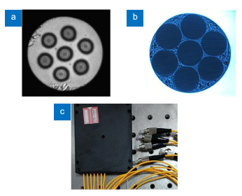
In addition, the fiber bundle coupling method is also a widely used solution, which has the advantage of robust and compact structure. In order to match the size and the spatial arrangement of cores of the MCF, the SMFs can either be tapered or etched to appropriate diameter, and then they are bundled as the core layout of MCF. Employing the chemical etching method, we have fabricated the SMFs bundle for the fan-in/fan-out coupler of the seven-core fiber, whose cross-sectional view is shown in Fig. 1(a)21-22. In our case, a portion of the cladding of the SMF is removed by chemical etching. Then seven etched SMFs are bundled with the cores arranged identically as that of the MCF, as shown in Fig. 1(b). The fabricated SMFs bundle is aligned with the MCF with the help of a 6-dimension free-space alignment platform, where a laser source and a power meter are used to monitor the performance of alignment between the cores of two ends. Eventually, the aligned two sides are fixed in a capillary tube by UV glue. In this way, a compact, robust and moveable fan-in/fan-out coupler is fabricated. The packaged fan-in/fan-out coupler is shown in Fig. 1(c), which consists of seven SMF pigtails and a MCF pigtail. The average insertion loss of cores could be less than 1.0 dB and the return losses of cores are all larger than 50 dB.
Figure 1.(a) Cross-sectional view of the fabricated 7-core fiber. (b) Endview of the 7-SMF bundle. (c) The packaged MCF fan-in/out coupler. Figure reproduced from ref.22, Optical Society of America.
There has been increasing interest in extending multicore fibers to distributed fiber sensing in recent years, particularly for three-dimensional (3D) shape sensing. This is because the MCF possesses the unique characteristic that the off-center cores are sensitive to bending, and it is realized that the differential strain between cores of the MCF can be used to retrieve its shape parametrically23. In addition, MCFs have also been used for the emerging SDM distributed fiber sensing, which usually employs two sensing techniques simultaneously through SDM system configurations or measuring two heterogeneous cores of a MCF to achieve multi-parameter sensing or enhanced sensing performance.
Bending induced tangential strain in off-center cores
Firstly, it is necessary to explain the mechanism of bending sensitivity of outer cores in MCF, which is the fundamental principle of many MCF based sensors. In the normal SMFs, the fiber core is located in the transversal geometric center along the whole fiber length, which is the strain neutral axis of the fiber, so bending will not generate strain in the fiber core of normal SMF. However, in a MCF that is subjected to bending, the cores at off-center positions will be either stretched or compressed, as shown in Fig. 224. Specifically, the cores on the outer side of the neutral plane will be elongated (e.g. core A in Fig. 2), while the cores on the inner side of the neutral plane will be compressed (e.g. core B in Fig. 2).
Figure 2.Schematic diagram of the bent MCF with a bending radius of R. Core A and Core B represent the elongated outer side core and the compressed inner side core, respectively.Figure reproduced from ref.24, Optical Society of America.
It indicates that either stretching or compression of the off-center fiber core will give rise to local tangential strain at the bending point, and it turns out that for a given fiber with specific bending curvature κ (the reciprocal of bending radius), the generated strain εi in a specific core i is angular position dependent, as given by23-25
where di is the distance of core i to the fiber center, R is the bending radius (κ=1/R),
θb is the bending angle and θi is the angular position of core i, as shown in Fig. 3. It should be pointed out that the local coordinate system is arbitrarily chosen, e.g. the line from core 4 to core 1 is selected as the x-axis of the system in Fig. 3, and the relative orientation between the axis and a specific core is assumed to be constant throughout the fiber once it is determined. θb is defined to be the angular offset from the local x-axis to the local fiber bending direction, and θi is the angle from local x-axis to a specific core i. Meanwhile, it is worth mentioning again that for the central core, since d=0, so ε=0, and that is why the central core is not sensitive to bending.
Figure 3.The transversal spatial distribution of cores of a seven-core fiber, showing the definitions of some important geometrical parameters.Figure reproduced from ref.25, Optical Society of America.
The bending induced tangential strain in off-center cores can normally be interrogated by ways of fiber Bragg grating, interferometer and Brillouin distributed sensing, etc. The unique bending sensitivity has been used to develop many sensing applications, as we will show in the following sections.
Discrete and continuous FBG arrays in MCF for 3D shape sensing
It turns out that the cores will normally subject to different strain caused by bending, unless they have the same radial distances and are within the same plane with respect to the bending plane. The differential strains between different cores have been used to parametrically reconstruct the shape of fiber in the 3D space23. This is enabled firstly through the measurements of bending induced strains based on axially co-located FBG array sensors in a MCF, and then the derived distributed curvature and bend orientation parameters are used to retrieve the overall 3D shape of fiber by solving the Frenet-Serret equations23, 26.
In order to calculate the bending parameters (curvature and bending orientation) using the information from N cores (N > 3), an apparent curvature vector ${K_{\hat i}}$ can be defined for each core i, and their sum is formulated as
where $\hat i$ and $\hat j$ are unit vectors aligned with the local x- and y-axis, respectively. The local bending angle ${\theta _{\rm{b}}}(z)$ and curvature $\kappa (z)$ can then be derived from Eq. (2), as given by23, 26
Once the curvature and bending orientation parameters are obtained, the shape of fiber can be reconstructed by solving a set of Frenet-Serret formulas, which involve three orthogonal vectors at each point of the curve, namely the tangent vector T(z), the normal vector N(z), and the binormal vector B(z), as given by
where τ(z) is the torsion function of the curve, and it can be obtained from the derivative of bending angle function with respect to curve length, i.e. τ(z)=θ′b(z). Providing an initial position condition after calibration, e. g. typically $\kappa (0) = 0$,
${\theta _{\rm{b}}}(0) = 0$, then the whole 3D shape of fiber can be retrieved numerically by integral23. Note that the twist effect is not considered in Eq. (5)26. By using this technology, fully 3D shape sensing has been demonstrated27, as shown in Fig. 426.
Figure 4.An example of multicore fiber-based shape measurement. Figure reproduced from ref.26, Optical Society of America.
As mentioned previously, in order to measure the bending induced strains that are used for shape reconstruction of the MCF, axially co-located FBG arrays are commonly used, as shown in Fig. 5. The linear FBG sensor arrays are inscribed into each core of a MCF with each FBGs group aligned in the same cross-section at each position. The spacing between two adjacent FBG groups determines the spatial resolution of strain measurements, which is normally high-density (e.g. typically 1 cm) in order to ensure high shape reconstruction accuracy28-29. Since the optical time-domain reflectometry (OTDR) technique is difficult to offer sub-meter spatial resolution, thus it is not suitable to read the large FBG arrays. On the other hand, the wavelength-division multiplexed FBGs scheme suffers from very limited multiplexing numbers of FBGs due to the finite bandwidth of laser source while the assignment of sufficient dynamic range for each FBG sensor is required. Eventually, OFDR technique turns out to be an excellent solution to interrogate the wavelengths of a large number of FBGs in the MCF28-30.
Figure 5.Strain measurements in a multicore fiber by using co-located fiber Bragg grating arrays for shape sensing.
OFDR uses a wavelength linearly swept narrow linewidth laser source in the system. The Rayleigh backscattering signals from the sensing fiber arm interference coherently with the light from the reference arm at the receiver. The generated interference signal contains the beat frequencies information, which can be obtained by Fourier transform. Since the laser is linearly scanned, the beat frequencies are proportional to the length of the sensing fiber. The spatial resolution of OFDR is determined by the frequency scan range of the laser, which can reach even tens of micrometers30. Thanks to the distance resolved capability with ultrahigh spatial resolution, OFDR allows thousands of FBGs to be interrogated even though they have overlapped spectra. For a FBG array in a fiber core, each FBG generates an interferogram with a specific beat frequency that is proportional to the optical path length, yielding the detected signal as given by31-32.
where Ri is the reflected spectrum of the ith FBG,
k is the wavenumber with $k = 2{\rm{ \mathsf{ π} }}/\lambda $, and $\lambda $ is the wavelength of light, no is the effective refractive index of the fiber, Li is the path difference of the ith FBG. By applying Fourier transform to the acquired waveform, a mapping of spatial frequency domain can be obtained, where each corresponding reflection represents each grating at its specific distance. A bandpass filter is then used to window the signal from each individual FBG. This data is then inverse-transformed and the spectrum of each individual FBG is recovered. By monitoring the spectral shift of each FBG, the strains at every discrete position can be determined.
The discrete FBG arrays can provide two-point strain spatial resolution of 1 cm29, which might still not be sufficient for high accuracy shape reconstruction in some cases. Because the algorithm used for shape reconstruction relies on the integral of the tangent unit vector that is derived originally from the discrete sets of strains, and it turns out that the angular errors will accumulate, which rapidly reduces the accuracy of the retrieved shape. In order to achieve dense sensing, alternative strain measurement can be carried out directly by using the intrinsic Rayleigh backscattering signals in optical fiber that is measured by OFDR. Since the Rayleigh backscattering is caused by random fluctuations in the index profile of fiber, which can be considered as weak fiber Bragg gratings with random periods. Similar to the measurement of the FBGs, OFDR is used to measure the Rayleigh backscattering as a function of length in optical fiber. The Rayleigh scattering pattern over small segments can be Fourier transformed to obtain the Rayleigh scattering optical spectrum for that segment. Then cross-correlation is performed between two sets of Rayleigh measurements, and shifts in the spectral pattern can be related to the change in strain for the specific fiber segment31, 33-35. The benefit of the intrinsic Rayleigh backscattering based strain measurement using OFDR is its ultrahigh strain spatial resolution (tens of microns), as a result the obtained more accurate locations of strain will help to improve the accuracy of shape reconstruction. But of course, the signal-to-noise ratio (SNR) of measurement by using this technique is not as good as the FBG based strain measurement.
Practically, in addition to bending, the shape sensing fiber may also have arbitrary twist along the fiber length, which causes additional strain in the fiber cores as well. So it is necessary to figure out the fiber torsion induced effect on the overall strain measurement in MCF. To do so, a kind of helical MCF with permanent twisted outer cores and a straight central core has been developed36-40, as an example shown in Fig. 6. Again, FBGs are inscribed in all cores and each set of FBGs are aligned at a common axial coordinate. Fiber torsion will lead to common-mode strains to each outer cores. Specifically, torsion adds tensile strain to all the outer FBGs as the fiber twists in the same sense as the helical bias, and torsion leads to compressive strain to all the outer FBGs if fiber twists in the opposite sense from the helix. Meanwhile, the central core serves as a reference to compensate for axial strain and temperature variations since it does not respond to bending or twist due to the reason that it is located on the neutral axis of the fiber. Eventually, the overall strain at each FBG consists of bending, torsion and thermal expansion induced strains, as given by37-38
Figure 6.Illustration of shape sensing using helical multicore optical fiber.(a) Microscope view of the four-core sensing fiber, sensing triad in red. (b) Illustration of helical cores along length of fiber. Figure reproduced from ref.40, SPIE.
where ΔT is the temperature variation; kT is the thermal apparent strain coefficient; εBending is bending caused strain; z is the twist-strain coefficient, and w is the applied twist. By calculating the equations of the co-located FBGs, the individual effect can be determined38. So the unique helical MCF can allow deduction of local "shape variables" - bending, twist, and temperature, which will help to achieve more accurate shape sensing.
As mentioned previously, the discrete FBG array- based strain measurement approach has the drawback of insufficient spatial localization resolution of strain, while the intrinsic Rayleigh backscattering based strain measurement scheme has low SNR. In order to improve the performance of shape sensing fiber, recently a helical MCF with continuous weak FBGs in all the cores has been proposed41-45. Fig. 7 shows a schematic of the inscription system that is used to write the grating arrays. The twist outer cores are produced by rotating the preform during fiber drawing, and continuous fiber gratings are fabricated using the reel to reel apparatus, which sends the MCF past a phase mask, so that the fiber is exposed to a UV interference pattern which gives rise to the desired grating spectrum in the fiber cores. Note that MCF has UV transparent acrylate coating. The fabricated MCF with continuous weak FBGs will allow for strain measurement with much higher spatial resolution in comparison with the discrete FBG array based measurement method. On the other hand, the gratings also increase the reflection signal notably, so strain measurement using Rayleigh backscattering directly through cross-correlation will achieve much higher SNR.
Figure 7.(a) Reel-to-reel array inscription apparatus allowing continuous fabrication of gratings in all cores through UV transparent coating. (b) End-view image of a seven-core fiber with coating removed.
(c) Twisted multicore fiber schematic showing UV transparent coating (right). Bare glass region (left) shown to highlight twisted multicore continuous gratings. Figure reproduced from ref.44, IEEE.
Distributed curvature and shape sensing using Brillouin scattering in MCF
In addition to the FBGs based MCF shape sensing scheme, Brillouin distributed sensing in MCF has also been employed for distributed curvature and shape measurement25, 46-47, because it is found that the Brillouin frequency shift (BFS) is bending dependent in off-center cores of the MCF. As shown in Fig. 8, a typical distribution of Brillouin gain spectrum (BGS) in an off-center core of a coiled seven-core MCF with ~15 cm spool diameter is presented46. Random BFS fluctuation with large excursion can be observed, which results from the local tangential strain induced by the fiber coiling with random azimuthal orientation. While the BFS of the central core is much more uniform, which is similar to the profile of any normal single mode fibers. This is because bending will not give rise to strain in the central core.
Figure 8.Top view of the Brillouin gain pectrum in an off-center core of the MCF showing bound random BFS variations resulting from bending due to fiber coiling. Figure reproduced from ref.46, IEEE.
The bending dependence of BFS in off-center cores is essentially caused by the local tangential strain when the fiber is under flexure. The strain leads to variation of BFS, as given by
where $\Delta {\nu _{{\rm{Bi}}}}$ is the change of BFS of core i, α is a to be determined response coefficient of bending induced strain, νB is the BFS of a straight fiber section. Specifically, the BFS experiences a down-shift when the off-center core is compressed and an up-shift when being stretched. In order to calibrate the curvature response coefficient of BFS (i.e. α), a conventional Brillouin optical time-domain analyzer (BOTDA) was implemented to measure the BFSs of an outer core under different bending radii, where a short section of 1.5 m MCF was employed to create a circle type bending with the circular bending radius being adjusted for different measurements. Precise alignment was carried out to make the selected outer core that was used for calibration to be positioned in the bending plane, so that θb-θi=0 or ${\theta _b} - {\theta _i} = 180^\circ $, thus the bending induced strain is only related to the bending radius for the specific core in this case, as can be seen from Eq. (1). The alignment is enabled by launching red light into the core, while a microscope was used to visualize the real positioning of the core, so that it securely lays in the applied bending plane. The measured BFSs under different bending radii are shown in Fig. 9(a), and Fig. 9(b) presents the BFS changes as a function of the applied bending curvature. Additionally, the BFS of the fiber without applied strain is measured to be 10.735 GHz. Eventually the variables of Eq. (8) can be determined. Then, it can be used to calculate the bending induced strains from the measurement of BFSs in different cores, which can further be utilized to achieve distributed curvature and shape sensing.
Figure 9.(a) Extracted Brillouin frequency shift for different bending radii. (b) Dependence of BFS on curvature measured along an outer core of the MCF. The error intervals on the curvature and the measured BFS are marked in green and purple triangle dots, respectively. Figure reproduced from ref.25, Optical Society of America.
With the calibrated coefficients, distributed curvature sensing has been demonstrated by using BOTDA in MCF. As shown in Fig. 10(a), three O-like shapes have been patterned at the far end of a 1 km long seven-core MCF. At these fiber sections the orientation of cores of the MCF was carefully positioned using the visual procedure, so that the bending angle along the whole interrogated fiber section was adjusted to be either 0 (or 2π) or π, with respect to the fiber core used as reference. Distributed measurements of BFSs in three adjacent outer cores have been carried out, as shown in Fig. 10(b), where bending induced BFS variations can be easily identified. 20 cm spatial resolution was achieved by using the differential pulse-width pairs (DPP) technique48. The measured BFSs are converted to strains using Eq. (8), and then the resolved strains are used to calculate the bending angle and curvature of each pattern by solving Eqs. (2)-(4). The retrieved bending angle and curvature as a function of fiber length around the applied shapes are presented in Figs. 10(c) and 10(d), respectively. The result indicates that the retrieved bending angles are either 2π (or 0) or π at the three O-like shapes, which is consistent with the calibrated position. On the other hand, the relative error in the radius R is calculated to be below 3.48 % for all the shapes, showing high accuracy and good reliability of the method for distributed curvature and shape sensing25.
Figure 10.(a) Three O-shapes made for validating the ability of distributed curvature and shape sensing based on BOTDA in MCF. (b) The measured BFS profiles as a function of distance along three cores around the 3 O-shape regions. (c) Retrieved bending angle for the 3 O-shape regions. (d) Retrieved curvature for the 3 O-shape regions. Figure reproduced from ref.25, Optical Society of America.
Once the bending angle and curvature along the whole fiber length have been retrieved, they can be used to calculate a set of Frenet-Serret formulas, i.e. Eq. (5), and give a calibrated initial position condition of the MCF; its 3D shape can be fully reconstructed. The benefit of FBGs based MCF shape sensing scheme is the ultrahigh spatial resolution, while the reported sensing range is normally short, typically several meters to a few tens of meters31, 40. In contrast, Brillouin distributed measurement based MCF shape sensing approach can obtain much longer sensing range, and it does not require any special processing like writing FBGs. However, the spatial resolution is bad, and it is very challenging to achieve comparable spatial resolution as the OFDR technique49. In addition, Brillouin distributed measurement is normally time consuming. As a result, real-time shape reconstruction will be difficult by using the Brillouin distributed measurement technique.
MCF space-division multiplexed distributed fiber sensors for multi-parameter sensing
MCF possesses multiple parallel spatial cores in a single fiber cladding, which provides an excellent platform to incorporate different sensing techniques in one fiber through SDM system configuration, so that the advantages of various sensing techniques can be combined in a single sensing system, which opens a new way to achieve advanced distributed sensing functionality. In addition, specially designed heterogeneous MCF can also be employed to achieve performance enhanced distributed sensing by using the differential responses of strain/temperature between cores. Some studies have been carried out by using MCF SDM sensing system to achieve temperature and strain discriminative measurement, simultaneous temperature and vibration sensing, vibration detection with broad frequency response range, temperature sensing with simultaneous large dynamic range and high measurement resolution, etc.
Firstly, it is well-known that the Brillouin scattering signal in optical fiber is intrinsically sensitive to both temperature and strain, which causes ambiguity in the determination of disturbances and has degraded dramatically the reliability of Brillouin distributed sensors in practical applications. In order to address this problem, several solutions have been reported, among which Brillouin and Raman hybrid system turns out to be a good scheme for temperature and strain discrimination50. Because Raman optical time-domain reflectometry (ROTDR) is only sensitive to temperature, so it can be used to determine the temperature effect and thus separate from strain in the Brillouin distributed sensors. However, it is difficult to measure simultaneously the spontaneous Raman scattering (SpRS) signal and Brillouin scattering signal in single mode fibers. Because SpRS is very weak, the Raman anti-Stokes signal is usually ~60 dB lower than the injected pump peak power51. So normally very high incident pump power (several Watts) is used in ROTDR sensors in order to increase the detected SpRS intensity. But on the other hand, Brillouin distributed sensors cannot use such high pump power due to the reason that the threshold of nonlinear effects, including modulation instability (MI), stimulated Brillouin scattering (SBS), is normally lower than the required power level of ROTDR52, which restricts the maximum usable input power in the hybrid system. Note that the Brillouin scattering trace could be dramatically affected by waveform distortion caused by the nonlinear effects, while the nonlinear tolerance of ROTDR is much higher since it relies on the detection of the power ratio of the broadband Raman Stokes and anti-Stokes signals which turns out to be not sensitive to the nonlinear effects.
In order to address the restriction in terms of the incompatible pump power levels of the Brillouin and Raman hybrid system in SMFs, MCF based SDM hybrid system has been proposed and demonstrated53. As shown in Fig. 11, the measurements of Raman and Brillouin scattering signals are carried out simultaneously in distinct cores of the MCF, so the input powers for the two branches can be controlled flexibly. The proposed hybrid system uses a single distributed-feedback (DFB) laser, shared pump generation devices, but separate interrogation fiber cores and different receivers, which allows for simultaneous measurement of SpRS and Brillouin scattering signals with identical spatial resolution. Eventually, temperature and strain discriminative measurement is achieved.
Figure 11.Experimental setup of the MCF based SDM ROTDR and BOTDR hybrid system. LD: Laser diode; PC: polarization controller; SOA: semiconductor optical amplifier; MZM: Mach-Zehnder modulator; EDFA: erbium-doped fiber amplifier; PS: polarization switch; BPF: bandpass filter; BPD: balanced photodetector; Att.: tunable attenuator; APD: avalanche photodiode; ESA: electrical spectrum analyzer; OSc.: oscilloscope; the inset shows the cross-section view of the used MCF in the experiment. Figure reproduced from ref.53, Optical Society of America.
For proof of concept, a seven-core fiber was used in the experiment, as shown in the inset of Fig. 11. In order to avoid bending imposed cross-sensitivity to BFS in off-center cores, the central core is selected to implement Brillouin optical time-domain reflectometry (BOTDR), and one outer core is used to conduct ROTDR, so strict quantitative discrimination between temperature and strain is ensured. The experiment demonstrated 3 m spatial resolution over 6 km sensing range with the worst temperature and strain resolutions of 2.2 ℃ and 40 με, respectively.
Another alternative solution to separate the effects of strain and temperature in Brillouin distributed sensors is to use two cores simultaneously, whose strain/temperature sensitivities are different54-58. This is achievable by using a heterogeneous MCF, whose cores are made from different preforms. Fig. 12 shows the cross-section view and the refractive index profile of a heterogeneous MCF56. The outer six cores are all made from G657.B3 preform (YOFC, China), and the central core is made from G.652 preform. Since the two kinds of cores have different doping, their refractive indexes are different as well, as shown in Fig. 12(b). As a result, ∼70 MHz BFS difference between the central core and the outer cores have been observed, as shown in Fig. 13.
Figure 12.(a) Cross-sectional view of the heterogeneous MCF, whose outer six cores are made from the same preform but the central core is made from another preform. (b) Relative index profile of the heterogeneous MCF. Figure reproduced from ref.56, Optical Society of America.
Figure 13.The measured BGS of a heterogeneous MCF. (a) The central core with peak at ~10.81 GHz. (b) The outer core with peak at ~10.74 GHz. Figure reproduced from ref.56, Optical Society of America.
Since the heterogeneous cores have different temperature and/or strain sensitivities, by measuring the BFSs of two cores simultaneously, discrimination can be achieved by calculating a coefficient matrix. However, in a MCF the off-center cores are also highly sensitive to bending, so firstly the bending induced BFS variation needs to be compensated. This can be done by averaging the BFSs of two symmetrical outer cores. Because bending will cause identical absolute value of BFS shifts, but with different shift directions. For two symmetrical outer cores of a MCF, their BFS shifts ($\Delta \nu _{\rm{B}}^{{\rm{out + }}}$ and $\Delta \nu _{\rm{B}}^{{\rm{out - }}}$) are caused by temperature, strain and bending, as given by
where $\Delta \nu _T^{{\rm{out}}}$ and $\Delta \nu _\varepsilon ^{{\rm{out}}}$ are temperature and strain induced BFS shift. Note that the angular positions of the two symmetrical outer cores can be depicted as θi and θi+π in the local x-y coordinate, so bending induced BFS shifts to the two outer cores are given by
where $\Delta \nu _{\rm{b}}^{{\rm{out + }}}$ and $\Delta \nu _{\rm{b}}^{{\rm{out - }}}$ are bending induced BFS shifts of the two symmetrical outer cores, α is the bending response coefficient, νB is the original BFS without bending nor strain. Noticing that $\Delta \nu _{\rm{b}}^{{\rm{out + }}} + \Delta \nu _{\rm{b}}^{{\rm{out - }}} = 0$, therefore averaging the BFS shifts of two symmetrical outer cores can completely remove the effect of BFS shifts due to bending in off-center cores, i.e.
This has been experimentally verified, as shown in Fig. 14. The measured BFSs of two symmetrical outer cores are plotted in blue and red traces. The MCF was spooled with random orientations, so the BFSs show random fluctuations due to bending. The green trace is the averaged BFS of the two cores, which turns out to be very flat and it is equal to the original BFS of the outer cores without bending. So it verifies that averaging the BFSs of two symmetrical outer cores can totally counteract the bending caused BFS variations.
Figure 14.The measured BFS of two symmetrical outer cores when the MCF was spooled with random orientations; the green trace is the averaged BFS of two symmetrical outer cores. Figure reproduced from ref.56, Optical Society of America.
Once the BFSs in three cores have been measured, including the central core and two symmetrical outer cores, then the strain and temperature can be separated by calculating the coefficient matrix, as given by
where $\Delta \nu _{\rm{B}}^{{\rm{cen}}}$ is the measured BFS of the central core, $C_T^{{\rm{cen}}}$, $C_T^{{\rm{out}}}$ are the measured temperature coefficients and $C_\varepsilon ^{{\rm{cen}}}$, $C_\varepsilon ^{{\rm{out}}}$ are the strain coefficients for the central core and outer cores, respectively.
Note that a MCF has certain advantage over the SMF bundle, since MCF contains all-solid cores, and their physical paths are strictly identical along the whole fiber length. For each position, the two cores experience identical temperature, and the relative distance between cores remains constant with respect to the input end. But the bundle of SMFs cannot be as compact and uniform as the MCF, especially along very long range, so error associated with fiber length mismatch will be generated, and the cores might undergo different temperatures due to distinct amounts of transformation from external disturbance. All these factors will eventually degrade the accuracy and reliability of the SMFs bundle based sensing system.
In addition to simultaneous temperature and strain sensing, other multi-parameter detections are also necessary in many industrial applications. For example, in oil and gas industry, simultaneous distributed intrusion detection and temperature monitoring of pipelines are required in order to achieve real-time alarm on excavation, theft, leakage and other potential threats. This can be done by implementing a ROTDR and phase-sensitive optical time-domain reflectometry (φ-OTDR) hybrid sensing system59, where the ROTDR is used to monitor the temperature change and φ-OTDR is used for real-time vibration detection. However, similar to the Brillouin and Raman hybrid system, it is difficult to implement a Raman and Rayleigh hybrid system by using SMF due to the incompatible pump power levels required by ROTDR and φ-OTDR. As a matter of fact, the spontaneous Raman anti-Stokes signal is usually ~30 dB lower than the Rayleigh scattering signal50. The high pump power required by ROTDR will generate nonlinear effects (e.g. MI and SBS) in the sensing fiber, which distort the trace of φ-OTDR, and eventually hinder the correct measurement of Rayleigh scattering trace52. So it turns out that it is difficult to measure simultaneously the SpRS signal and the Rayleigh scattering signal in SMF.
Space-division multiplexed ROTDR and φ-OTDR hybrid sensor using MCF has been proposed and demonstrated60-61. As shown in Fig. 15, only one laser source is used in the system, and the generated pump pulse is shared for ROTDR and φ-OTDR, but the interrogations of SpRS signal and the Rayleigh scattering signal are carried out in different cores of the MCF, the detection and acquisition of two branches are also separated and complete independent.
Figure 15.Experimental setup of the MCF SDM ROTDR and φ-OTDR hybrid sensor. LD: Laser diode; PC: polarization controller; SOA: semiconductor optical amplifier; PG: pulse generator; EDFA: erbium-doped fiber amplifier; BPF: band-pass filter; OC: optical coupler; Att.: tunable attenuator; APD: avalanche photodiode; PD: photodetector; OSc.: oscilloscope; the inset shows the cross sectional view of the seven-core MCF. Figure reproduced from ref.61, IEEE.
Since the off-center cores of the MCF is highly sensitive to bending, so the outer cores rather than the central core are preferred to implement φ-OTDR, thus sensitivity enhanced vibration sensor can be obtained. 3 m spatial resolution over 5.76 km sensing range was demonstrated in the experiment. The proposed MCF based hybrid sensing system allows for simultaneous distributed temperature sensing (DTS) and distributed acoustic sensing (DAS), which shows great potential for long-range real-time pipeline monitoring in oil and gas industry.
Enhance the performance of distributed fiber sensors by using MCF space-division multiplexed configurations
As mentioned previously, MCF allows for space-division multiplexed sensing deployment configurations that might incorporate different sensing techniques, which has turned out to be a very good way to enhance the performance of distributed fiber sensors. For example, although φ-OTDR has attracted a lot of research interest in recent years, due to its great potential in the applications of intrusion detection, structure health monitoring and seismic monitoring, etc., the maximum detectable vibration frequency of φ-OTDR is however ultimately limited by the repetition rate of the used pump pulse, which is an intrinsic shortcoming of this technology. In order to address this restriction, a hybrid φ-OTDR and Mach-Zehnder interferometer (MZI) sensor using SMF has been proposed62, where the φ-OTDR is used to locate the vibration position, and the MZI is used to retrieve the vibration frequency. Since the maximum detectable vibration frequency of the hybrid system is determined by the sampling frequency of the oscilloscope and the bandwidth of the photodetector, the hybrid system can achieve very broadband frequency response. However, in the SMF based hybrid system, the backscattered light from the offset CW light results in very bad SNR of the positioning signal, and the weak optical power of the interference signal results in noisy signal power spectrum. Moreover, superposition of the pulse on the MZI interference spectrum also increases the complexity of data processing.
Instead of sending both a pulse and a continuous-wave light into only one SMF, which are used for φ-OTDR and MZI, respectively, it is realized that the problems of the SMF based hybrid system can be eliminated by implementing the two sensors in different cores of a MCF63. As shown in Fig. 16, in the MCF based hybrid sensing system, two cores can be used to construct the MZI sensor, so no reference fiber is needed. Because the off-center cores are sensitive to bending, the bending induced differential strain between the two cores will make the MCF based MZI sensitive to vibration. The output of MZI can be delivered to the transmitter side through the third spatial core, so it enables single-end access. Meanwhile, φ-OTDR is implemented in another core, which is used to locate the vibrations.
Only one laser source is required in the MCF based φ-OTDR and MZI hybrid sensing system, but they are carried out in different cores, the detections and acquisitions are also separated, which effectively eliminates the restrictions of the SMF based hybrid system. Eventually, 2.42 km sensing range with 1 m spatial resolution and up to 12 kHz (limited by the electrical cut-off frequency of the voltage driver of the piezoelectric transducer) vibration sensing was demonstrated in the experiment.
In addition to the widely used application field of vibration detection, φ-OTDR can also be used for temperature and strain measurement, where frequency sweeping over a spectral range is required in order to obtain the mapping of Rayleigh backscattering signal as a function of fiber length and optical frequency, and then cross-correlation is calculated between two sets of measurements. The relative temperature/strain change can be retrieved from the frequency shift of cross-correlation peak64. The technique can offer ultrahigh temperature/strain measurement resolutions, which are 0.01 ℃ and 0.1 με, respectively, or ever higher65. So it shows great potential in distributed sensing applications that require high measurement resolution. But its measurement dynamic range is normally small, which is determined by the frequency scanning range, and typically the range is from hundreds of megahertz to several gigahertz. On the other hand, although Brillouin distributed sensors have been intensively investigated in the last three decades, owing to their outstanding sensing performance on temperature and strain over a wide measurement dynamic range with long sensing distance and high spatial resolution, the Brillouin distributed sensors suffer from the poor temperature/strain measurement resolutions, which are normally 1 ℃ or 20 με, respectively66. The poor measurement resolution restricts the application of Brillouin distributed sensors in some specific fields.
In order to achieve high measurement resolution and large dynamic range simultaneously, a SDM φ-OTDR and BOTDA hybrid sensing system by using MCF has been proposed and demonstrated67. As shown in Fig. 17, only one distributed feedback (DFB) laser is used in the system, and the generated pump pulse is divided into two branches for the φ-OTDR and BOTDA, respectively. The frequency sweepings of φ-OTDR and BOTDA are carried out by different modulators, because of distinct frequency scanning step demands. For BOTDA, the frequency sweeping step is typically 1 MHz or 2 MHz; while it is normally 10 MHz, 15 MHz or 20 MHz for the φ-OTDR. Eventually, φ-OTDR and BOTDA are implemented in different cores of the MCF.
Figure 17.Experimental setup of the MCF based SDM hybrid BOTDA and φ-OTDR sensing system. LD: Laser diode; PC: polarization controller; SOA: semiconductor optical amplifier; MZM: Mach-Zehnder modulator; EDFA: erbium-doped fiber amplifier; PS: polarization switch; Att.: attenuator; PD: photodetector; Fan-in: fan-in coupler; Fan-out: fan-out coupler. Figure reproduced from ref.67, Optical Society of America.
In the MCF based SDM hybrid sensing system, the BOTDA is used to provide measurement over large dynamic range and the φ-OTDR is dedicated to offer measurement with high resolution. So the hybrid system combines the complementary advantages of the two sensors. Experiment demonstrated 2.5 m spatial resolution over 1.565 km MCF with about 0.001 ℃ temperature uncertainty, showing good feasibility to measure both large and very small temperature variation by using the hybrid sensing system, so it is believed that the proposed system will have great potential in a wide range of applications.
In addition to the previously mentioned applications, MCF also has the potential to be used to implement a double-ended (loop-back) DTS sensing system. Since in ROTDR sensors, the different wavelength dependent loss (WDL) between the Raman Stokes and anti-Stokes components will cause error in the determination of temperature. So the MCF based double-ended DTS system can help to eliminate the WDL induced temperature error68.
Challenges and prospects
Currently there is still no industrial standard for the design of MCF; as a result, the parameters of MCF (e.g. fiber cladding size, core-to-core pitch, refractive index profile, etc.) are different from manufacturer to manufacturer. This has led to incompatibility among MCF components. More importantly, the fabrications of critical optical modules of the MCF based SDM system (e.g. MCF multiplexer/de-multiplexer, MCF amplifier, etc.) are not mature yet. So far, these devices are normally home-made or customized. Although both the waveguide coupling and fiber bundle coupling based MCF fan-in/fan-out couplers have been commercialized by a few companies, e.g. YOFC China69, Chiral Photonics70, Optoscribe71, etc. The commercially available fan-in/fan-out couplers normally have about 1 dB average insertion loss per channel. So it turns out that this critical optical device still suffers from high insertion loss. In addition, splicing two MCFs normally adds about 0.1 dB to 0.5 dB loss or even more to each channel72. As a result, both the insertion loss of MCF coupler and the splicing loss within the fiber link will degrade the SNR of the measured scattered signals, which becomes one of the major limiting factors in the high spatial resolution distributed sensing systems, e.g. a BOTDA sensor that uses differential pulse width technique48. On the other hand, there might be strong reflection as well that is caused by the fan-in/fan-out coupler, which will give rise to an interference noise that overlaps with the scattering trace, and it will lead to intensity fluctuation, thus increasing the uncertainty of the measurements. This is another major limiting factor that will degrade the performance of distributed MCF sensors. Therefore, it turns out that it is important that the fabrication processes of the MCF and the performance of the relevant optical components should be further improved.
MCF has been demonstrated to achieve long range and distributed curvature measurement with good reliability, but it is still very challenging to obtain long distance and high accuracy 3D shape sensing. It is realized that the accuracy of the shape sensing relies highly on the measurement accuracy of strain along the MCF, because shape reconstruction is achieved by integration from the initial position to the fiber end, which is based on the discrete sets of strains derived vectors along the MCF. Therefore, highly accurate strain measurement is essential to ensure precise shape reconstruction. Practically, since both techniques (FBG/OFDR and Brillouin distributed sensor) have a minimum detectable curvature variation, they are not able to sense very small shape change, which may restrict their application. It is worth mentioning that in order to increase the sensitivity of bending sensing, the outer cores of the MCF can be fabricated with larger distance from the fiber center, as it can increase the response to bending as inferred from Eq. (1).
For the temperature and strain discriminative measurement method based on heterogeneous MCF, the two disturbances are separated from the differential response between cores by calculating the coefficient matrix (i.e. Eq. (12)). However, the sensitivities between the cores are still very close, which will lead to a relatively large discrimination uncertainty. In order to decrease the uncertainty, the temperature/strain sensitivity difference between the heterogeneous cores needs to be increased, and this might be done by changing the doping of the cores or employing different materials for the cores.
It has been demonstrated that the MCF based SDM sensing system can help to solve some problems of the SMF based distributed sensing system, or to achieve performance enhanced distributed sensing. It is believed that MCF will find more sensing applications in the future. Firstly, the current work can be further extended to achieve real-time long range and distributed curvature sensing, which may find applications in aerospace industry. MCFs offer the unique possibility to realize differential and common-mode measurements between cores, which can be used to achieve multi-parameter discriminative distributed sensing. The angular position dependent bending sensitivity of off-center cores may be explored to achieve vector distributed vibration sensing, where the vibration direction might be determined from the differential response between cores. Since the MCF can be configured with a round-trip setup by connecting several cores simultaneously, it will even be possible to trace the evolution of measurands, since light will successively pass through different cores of MCF within a very short time. In addition, it will also be very interesting to explore the optomechanical effects based on either inter-core cross-talk or forward stimulated Brillouin scattering in MCF for sensing73-75, which may find various applications in the oil and gas and energy industry, oceanography, leak detection, structural health monitoring, etc.
Conclusions
In conclusion, a review on the MCF based distributed fiber sensing is presented in this paper. As an emerging and promising research area, brief introductions of MCF and the multiplexing/de-multiplexing methods are firstly presented. Then the bending induced tangential strain in off-center cores of the MCF is analyzed thoroughly. Parametrical 3D shape sensing using discrete and continuous FBG arrays in MCF is reviewed, which is followed by the alternative Brillouin distributed measurement enabled curvature and shape sensing solution. Thanks to the bending sensitivity in off-center cores, MCF manages to provide geometric differential response that allows for retrieving fiber bending related parameters, e.g. curvature and shape, etc. The unprecedented capability of distributed curvature and 3D shape sensing by using only one fiber has shown great potential in many industry applications, and has significantly expanded the functional diversity of optical fiber sensors. In addition, a variety of space-division multiplexed distributed fiber sensors using MCF are also summarized in this paper. The review reveals a novel perspective to implement distributed fiber sensing through SDM configuration rather than using a single fiber core, which offers a new approach to combine the advantages of various sensing techniques (e.g. BOTDR, BOTDA, ROTDR, φ-OTDR, and interferometers, etc.), and opens a new way to achieve advanced sensing functionality, e.g. enabling multi-parameter sensing and achieving performance enhanced distributed sensing.
Distributed fiber sensing using MCF has been a fascinating research field. It is believed that in the future, the SDM sensing systems will benefit a lot from the standardization of fiber manufacture and the improvement of SDM components (e.g. MCF multiplexer/de-multiplexer, MCF amplifier, etc.). In addition, MCF is expected to play a more important role in distributed multi-parameter sensing that allows for simultaneous measurement of several parameters, as well as in eliminating the cross-sensitivity between the parameters. By making use of the bending sensitivity of the MCF, it is believed that there will be more exciting research coming out. Hopefully, MCF will open up a new field of research that allows for distributed lab-on-fiber sensing.
Acknowledgements
This work was supported in part by the GRF project PolyU 152168/17E and PolyU 152658/16E of research grant council, Hong Kong SAR and 1-ZVGB, 1-YW3G, 4-BCCK of the Hong Kong Polytechnic University; National Natural Science Foundation of China under Grants 61331010, 61722108, U1701661 and 61435006.
Competing interests
The authors declare no competing financial interests.
[5] Ryf R, Sierra A, Essiambre R J, Gnauck A H, Randel S et al. Coherent 1200-km 6x6 MIMO mode-multiplexed transmission over 3-core microstructured fiber. In Proceedings of 37th European Conference and Exhibition on Optical Communication 1-3 (IEEE, 2011).
[6] Gonda T, Imamura K, Sugizaki R, Kawaguchi Y, Tsuritani T. 125 μm 5-core fibre with heterogeneous design suitable for migration from single-core system to multi-core system. In Proceedings of 42nd European Conference on Optical Communication 1-3 (IEEE, 2016).
[7] Proceedings of Optical Fiber Communication Conference/National Fiber Optic Engineers Conference PDPB6 (Optical Society of America, 2011); https://doi.org/10.1364/OFC.2011.PDPB6.
[8] Proceedings of 38th European Conference and Exhibition of Optical Communication Th.3.C.1 (Optical Society of America, 2012); https://doi.org/10.1364/ECEOC.2012.Th.3.C.1.
[36] Proceedings of Nonlinear Photonics JWA39 (Optical Society of America, 2007); https://doi.org/10.1364/BGPP.2007.JWA39.
[37] Proceedings of the 21st Annual Meeting of the IEEE Lasers and Electro-Optics Society 109-110 (IEEE, 2008); https://doi.org/10.1109/LEOS.2008.4688512.
[38] Askins C G, Miller G A, Friebele E J. Bend and twist sensing in a multiple-core optical fiber. In Proceedings of the Optical Fiber Communication Conference/National Fiber Optic Engineers Conference OMT3 (Optical Society of America, 2008).
[39] Proceedings of Imaging and Applied Optics AIMB2 (Optical Society of America, 2011); https://doi.org/10.1364/AIO.2011.AIMB2.
[43] T Kremp, K S Feder, W Ko, P S Westbrook. Performance characteristics of continuous multicore fiber optic sensor arrays. Proc SPIE, 10058, 100580V(2017).