
Juan Li, Hao Yu, Tiancheng Yu, Yudan Gou, Huomu Yang, Jun Wang. Design of high efficiency diode laser module for wireless power transmission[J]. Infrared and Laser Engineering, 2021, 50(5): 20210147
- Infrared and Laser Engineering
- Vol. 50, Issue 5, 20210147 (2021)
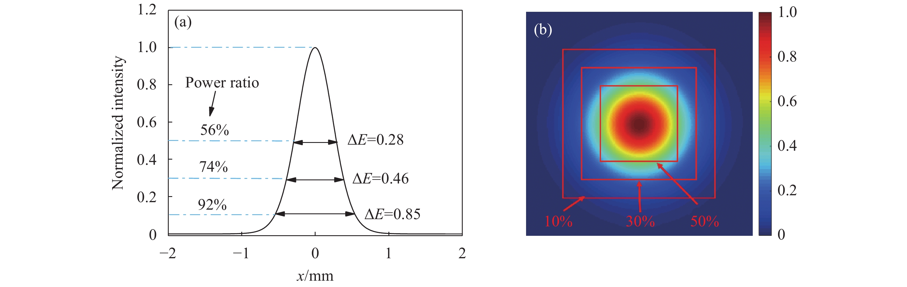
Fig. 1. The far-field spots and intensity distribution curve of Gaussian beam. (a) The far-field intensity distribution curve of Gaussian beam; (b) The far-field spots of Gaussian beam
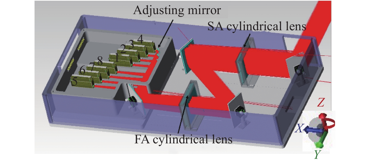
Fig. 2. Optical simulation of laser system
Fig. 3. Optical simulation at the receiver. (a) Optical field distribution of output beams from eight modules respectiveliy; (b) Optical field distribution of laser system in different sizes
Fig. 4. The effect of angle deflection on the optical field distribution at the receiver. (a) The unevenness distribution was obtained by optimizing the combination of 8 modules with deflection angles respectively; (b) Optical field distribution when the spot unevenness reaches the minimum; (c) Optical field distribution when the spot unevenness reaches the maximum
Fig. 5. The effect of defocusing of FA cylindrical lens on optical field distribution at receiver. (a) The relationship between the unevenness and the moving distance of lens; (b) The optical field distribution when the lens moves in the opposite direction of beam propagation to the beam outlet (−0.08 m), and the unevenness is 0.227; (c) The unevenness reaches the minimum which is 0.218; (d) The optical field distribution of the lens with a distance of 0.08 m in the direction of beam transmission, and the unevenness is 0.237
Fig. 6. The influence of the power variation of each module on the optical field distribution of the receiver. (a) The unevenness distribution was obtained by optimizing the combination of 8 modules with different output power respectively; (b) Optical field distribution when the spot unevenness reaches the minimum; (c) Optical field distribution when the spot unevenness reaches the maximum
Fig. 7. The far-field spots and intensity distribution curve of different beams. (a) The far-field intensity distribution curve of the output beam from diode laser system for short distance LWPT at the receiver; (b) The far-field spots of the output beam from diode laser system for short distance LWPT at the receiver
Fig. 8. Laser system output characteristics. (a) LIV curve of laser system; (b) The spectral characteristics of the laser system vs the operating current
Fig. 9. Measure of optical field distribution which is transmitted beyond 20 m under working current. (a) Optical field distribution of 20 m transmitted by 8 sub-beams; (b) The optical field distribution of laser system, which is transmitted beyond 20 m, and the spot size is 0.44 m×0.49 m
Fig. 10. The optical field distribution of laser system after optimizing, which is transmitted beyond 20 m


Set citation alerts for the article
Please enter your email address

© Copyright 2018-2021 | Chinese Laser Press. All Rights Reserved 沪ICP备15018463号-20