For the traditional Fabry-Perot cavity laser, the field perpendicular to cavity wall will be resonantly enhanced until it breaks with the threshold and escapes out of the cavity, while the field emitted obliquely dissipates outside the cavity leading to the low efficiency. Here a high-efficiency laser cavity is proposed resorting to metamaterials. Based on the multipath positive feedback mechanism, the photons emitted form atoms in any direction can only leak out of the cavity along one direction and no photons run out of the cavity which showed potential for improving the efficiency. Furthermore, this combination of cavity is almost independent of atom position. In addition, we designed a realistic dielectric micro-structure system made of two-dimensional photonic crystals to confirm our proposal. When the gain medium is introduced into the system, the cavity can provide both a lower lasing threshold and a higher maximum emission intensity, compared with the individual zero-index materials cavity, demonstrating improved lasing efficiency.
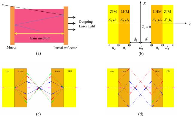
For traditional Fabry-Perot cavity lasers,photons propagate in any direction in the gain medium. In the cavity,only the photons(solid yellow arrows)that oscillate between the axis of the cavity with sufficient time can produce the laser effect. Meanwhile,the lasing direction can be to determined[1]. However,the photons that do not propagate along the cavity axis will be dissipated from the cavity,as shown by the black dashed line in Fig. 1(a). In other words,only electromagnetic waves of a particular direction and phase will be selected and emitted when a certain intensity threshold is reached. This cavity provides a single path positive feedback mechanism and the efficiency is low.
Figure 1.(a)Traditional Fabry-Perot cavity laser,(b)scheme of a Fabry-Perot cavity constituted of LHMs and ZIMs slabs,(c)and(d)the geometric optical-path of the radiation field emitted by the atoms,(c)atom is located in the center of the cavity,(d)atom is placed at(0,0,λ0),the black short arrow refers to atom
By introducing a defect in a periodic photonic crystal lattice,a microscopic counterpart to a Fabry-Perot cavity can be founded. The multidirectional distributed feedback effect occurring at frequencies close to the band edges of a defect-free photonic crystal slab can be used. The slow group velocity enables control of the lasing direction and polarization over large areas[2-3].
The metamaterials contain the zero-index materials(ZIMs)and the left-handed materials(LHMs)or negative-index metamaterial(NIM). The LHM is an artificial material that has both effective negative permittivity and negative permeability. Particularly,Pendry proposed that LHMs whose permittivity and permeability equal to -1 simultaneously can be used to construct a perfect lens,which is proved that the lens of negative refraction and phase compensation can be realized by dielectric photonic crystal(PC)[4-9]. In the meantime,the refractive index of ZIM is almost zero at the frequency of interest. The light inside the ZIMs has no spatial phase variation and extremely high phase velocity. These characteristics can be used to customize the radiation phase pattern[10],squeeze electromagnetic waves[11] and Directional radiation[12-14].
The negative-index property of double-negative metamaterials and the effective matching property of single-negative metamaterials can be used to serve the purpose of achieving ultrathin laser cavities[15]. Open and partially closed cavities are taken into consideration. Thus,with a variety of metamaterial combinations,resonant enhancement of the output fields is shown in both cases. In 2019,Tennant B A presented a new type of distributed feedback laser whose optical feedback is due to the evanescent coupling between an active positive-index material waveguide and a lossy NIM waveguide[16].
ZIMs can also be realized by two-dimensional(2D)dielectric PC[17-20]. In 2013,Moitra P et al. demonstrated an impedance-matched ZIMs cavity,based on two-dimensional PC structures[21]. When the quantum dots are embedded in the structure,the cavity can be used as an angle filter and enhances the direction of emission. Furthermore,the radiation angle is not dependent on the position of the light source in the ZIMs. In 2019,Peng Y et al. presented a 1550 nm laser based on the three-dimensional zero-index material[22]. Such phase coherence mechanism of the ZIM laser differs significantly from the Fabry-Perot cavity laser. The field pattern,transmission/reflection and the lasing threshold of ZIM laser is obtained.
In the letter,we have established a new kind of cavity made of metamaterials,which can prevent the obliquely emitted photons from leaking out of the cavity,thus greatly improve the output efficiency. When an excited two-level atom is located in the cavity,all photons emitted in any direction can finally leak out the cavity along the cavity axis with very high efficiency. In addition,the scheme does not depend on the position of the atom.
1 Physical model analysis
1.1 Model
The scheme for the cavity composed of LHMs and ZIMs slabs is shown in Fig. 1(b)[23]. The thicknesses of LHMs and ZIMs slabs areand,respectively. The cavity length is noted as ,which is twice the thickness of LHMs slab(i.e. )for the purpose of using the focusing effect formed by the LHMs and the air layer in the cavity. The permittivity and permeability of LHMs and ZIMs is ,,respectively. The middle white region is a vacuum. Take the center of the cavity as the origin of the coordinates. At the position of ,a two-level atom with transition frequency is placed in the cavity.
1.2 Physical mechanism analysis.
Fig. 1(c)and Fig. 1(d)describe the geometric optical-path of the radiation field emitted by the atoms,which is located at two different positions. When an excited two-level atom is located in the center of the cavity,as shown in Fig. 1(c),photons emitted along the cavity axis could pass through the cavity wall and leak out the cavity. However,the photons,whose propagation direction is not completely perpendicular to the cavity wall,will be refocused at the atom and emitted again,benefiting from the focusing and phase compensation effect of LHMs. After several cycles(feedback),the photons can finally escape out of the cavity when it's launched horizontally. If the atom is located a quarter of the length of the cavity from the left inner interface,as shown in Fig. 1(d),similarly,the obliquely emitted photon can be drawn back to the atom again with four focal points,and it can finally escape out of the cavity.
In a word,when the atom is located in the LHMs-ZIMs cavity,the photons emitted in any direction could be eventually escaping from the axis of the cavity with almost 100% efficiency and no photons are dissipated outside the cavity. The LHMs-ZIMs cavity provides a multipath positive feedback mechanism and prevents the obliquely emitted field from dissipating outside the cavity.
1.3 Numerical analysis.
The above is based on the analysis of classical optical paths. To confirm our forecast,the spontaneous emission field of the atom is calculated. Consider calculating the electromagnetic field of an oscillating current that is located in an inhomogeneous linear dielectric system composed of uniform isotropic regions. The system's response to harmonic disturbances can be described by a piecewise-defined dielectric function dependent on position. On the basis of Maxwell’s equation,the electric field of the oscillating current satisfies the following equation[24],
,
in connection with appropriate asymptotic conditions and the usual boundary. Where
,
it satisfies
⃡⃡⃡,
Where,⃡is the Green function for the system,⃡is the unit dyadic.
⃡⃡⃡⃡⃡⃡⃡⃡⃡
Without the external field, is given by the following formula
⃡ .
Furthermore,according to formula(4),it satisfies the boundary conditions of the outgoing wave and exponentially decaying wave of infinity. Without solving(2)to get the Green's function,it can equivalently establish the fieldof an oscillating point dipoleP0 that is embedded at position in the system. According to formula(4),and the dipole current density
.
Here,when =0,the dipole fields and Green's function are connected by
⃡ .
2 Numerical analysis.
2.1 Comsol simulation.
To validate theoretical analysis,COMSOL Multiphysics based on the finite element method is used to obtain atomic emission field. The length of the cavity is chosen as. For the LHM slabs and their thickness is. Meanwhile,the ZIM slabs possesses and. The intensity distributions of the atomic radiative field inside the cavity is shown in Fig. 2.
Figure 2.(Color online)The radiated electric field distribution by atomic when the electric point dipole is located in the center of the cavity(a)or located at(0,0,λ0)in the cavity(c). Far-field distribution of various radiation angles in the x-z plane is shown in(b)and(d),respectively. The white dotted lines in(a)and(c)refer to the interfaces between different materials
Fig. 2(a)is the electric field distribution of a point electric dipole located in the center of the cavity . Here,an electric point dipole is used to mimic a two-level atom. It is obvious the atomic radiate field is refocused at the position of atom. In addition,there are other two focal points located at the boundaries of LHMs and ZIMs,and the atomic emission field is trapped in the cavity. The results are consistent with those of geometrical optics shown in Fig. 1(c). Fig. 2(b)is the corresponding far-field radiation modes of Fig. 2(a). It is obvious the photons can escape from the cavity at a narrow radiative angle,which is less than 10o. From Fig. 2(c),it can also observe that when the atom is placed at another position in the cavity,the photons emitted into an arbitrary direction are refocused at the location of the atom,meanwhile there are four focuses. It is clear that the radiation field emitted by the atom can still be captured by the LHMs-ZIMs cavity which is consistent with the results of geometric optics shown in Fig. 1(d). Fig. 2(d)is the corresponding far-field radiation modes of Fig. 2(c). Obviously,the photons can escape out of the cavity at a narrow radiative angle.
Consequently,the simulation results of the atomic emission field are consistent with the geometrical optics results shown in Fig. 1(c)and Fig. 1(d). In addition,the emission profile is limited to an overall angular spread of 10O and is not sensitive to the position of the dipole.
In Fig. 3,the field is shown in logarithmic function,i.e. log(|E(r)|/E0),the unidirectional emission of the beam transmitted out of the cavity is obvious. The transmission beam is a Gaussian beam and the waist of the Gaussian beam increases in distance. The waist radius of the Gaussian beam is proportional to the divergence angle.
Figure 3.(Color online)The normalized expect value of atomic radiative electric field in logarithmic function(a)the atom is placed at ra=(0,0,0),(b)the atom is placed at ra=(0,0,λ0),the common parameters are the same to these in Fig. 2
S()is the angle spectrum of decay rate which shows the contributions to these modes which possess wave vector with azimuthal angle. In Fig. 3(a),S()is almost concentrated near =0o. Considering the rotational symmetry its FWHW is 2o which agrees with the beam shape of Fig. 3(a). In Fig. 3(b),the corresponding angle spectrum of decay rate has the similar distribution as that in Fig. 3(a).
Therefore,the atomic position has little influence on the unidirectional property of escaped photon for certain structure.
2.2 Realistic micro-structure system.
Finally,a realistic micro-structure system is designed to confirm our proposal. LHMs and ZIMs slabs are designed by employing dielectric PC and numerically demonstrate our theoretical results by using commercial electromagnetic software(CST),which uses finite integration time-domain numerical techniques to numerically solve Maxwell's equations. The operating wavelength is set as. LHMs is constructed by a 2D-PC made of a hexagonal lattice of circular air holes with the radius r1,drilled in dielectric substrates with permittivity=10.6. For r1=0.365a1,where a1=482 nm denotes the lattice constant[25]. And a 2D square lattice PC is used to achieve ZIMs. For the 2D square lattice PC the lattice constant is denoted as a2=r2/0.2. The radius,relative permittivity and permeability of the cylinders are set as r2=175 nm,= 12.5,= 1,respective [26].
For simplicity,an oscillating electric dipole is placed perpendicular to the plane with in the middle of the entire structure,and the radiation field distribution was calculated and is shown in Fig. 4. As predicted,the radiation field converges on three points,two are near the boundary of LHM and ZIM which is the proof of the behavior of LHM. Other one is at the atomic position. In addition,the electromagnetic(EM)field is intensively localized in the NIMs-ZIMs cavity. Conversely,the two beams are emitted along the x-axis(horizontal axis)outside the cavity,which confirms the collimation effect of ZIM. The results show that the simulation results of realistic micro-structure system are consistent with the simulation results as shown in Fig. 2. Thus,we can use the actual material to achieve the NIMs-ZIMs cavity.
Figure 4.(Color online)The radiative field distribution of an electric dipole placed in the middle of the structure constituted by two-dimensional P C. The operating wavelength is λ=1 500nm
To sum up,compared with the conventional Fabry-Perot cavity,the NIMs-ZIMs cavity provides a multipath positive feedback mechanism,which can prevent the field emitted obliquely to dissipate out of the cavity and greatly improve the output efficiency. Furthermore,the EM field is intensively localized in the cavity. The strong constraint of EM field is essential for the interaction between the light and the gain medium. Therefore,such a scheme can be treated as a good candidate for laser applications. The NIMs-ZIMs cavity is expected to improve the lasing behavior and decrease the lasing threshold.
3 Lasing action
As follows,the gain medium is introduced into the realistic microstructure system to prove the enhanced laser effect. When the gain medium is embedded into the NIMs-ZIMs cavity and optically pumped,the emission spectrum obtained is shown in Fig. 5. For gain material,a four-level two-electron atomic system with the following rate equations is used to describe the time evolution of the population density [27,28]
,
,
,
,
Figure 5.(Colour online). Lasing actions in the NIMs-ZIMs structures,(a)emission spectra of the NIMs-ZIMs cavity vary with input pump amplitude and wavelength,(b)emission spectra linewidth varies with pump amplitude
where the transition frequency between states 1 and 2,and that of state 0 and 3 are denoted byand,respectively. and denote the net macroscopic polarization of the transition from state 1 to state 2,and from state 0 to state 3,respectively. The level transition lifetime between x and y is expressed by. N0,N1,N2 and N3 correspond to the population densities of the molecules of the energy levels 0,1,2 and 3,respectively. The total electric field is denoted by. In the simulation,the other parameters of gain medium used are as follows
The relationship between the emission spectrum of the NIMs-ZIMs cavity and the incident pump intensity and wavelength is shown in Fig. 5(a). In the vicinity of 1 500 nm,the emission spectra with significant threshold behavior were observed,indicating the presence of lasing behavior. In order to show the enhanced lasing action more explicitly,the relationship between the linewidth of the emission spectra and the incident pump amplitude is given in Fig. 5(b). It is found that the linewidth of the excitation spectrum varies from about 3.8 nm to 0.6 nm,which is almost an order of magnitude narrower. This phenomenon clearly demonstrates a coherent lasing behavior[29].
By extracting the peak values of the spectra in Fig. 5(a),the maximum emission intensity varies with the amplitude of pump amplitude can also be plotted with the red solid line,which is shown in Fig. 6. For comparison,the spectrum of the ZIMs cavity is also plotted with the black dashed line. It can be found that the curves have the same trend of change in these two cases. Initially,the emission is close to zero below the threshold,then the value rapidly rises with the increase of the incident pump amplitude. However,their thresholds and peaks are significantly different from these two cases. The estimated threshold for ZIMs and NIMs-ZIMs structure are approximately as V/m and V/m,respectively. The results indicate that the threshold of NIMs-ZIMs structure is almost lower by one order than that of ZIMs. Meanwhile,a significant laser enhancement effect can be observed as the pump amplitude increases.
Figure 6.(Colour online)Maximum emission intensity varies with the input pump amplitude,black dashed and red solid lines represent individual ZIMs and NIM-ZIM structure,respectively
In conclusion,a high-efficiency laser cavity based on the utilization of metamaterials is proposed. Compared with the conventional Fabry-Perot cavity in which photons emitted obliquely cannot be collected,the NIMs-ZIMs cavity provides a multipath positive feedback mechanism,the photons emitted in the arbitrarily direction by the atom can only leak out the cavity unidirectional and there are no photons dissipates out of the cavity which enhances the output efficiency. In addition,this scheme is almost independent of the position of the atom. Afterwards,NIMs-ZIMs cavities made of 2D dielectric photonic crystals are realized by realistic microstructure systems. Then,gain medium is introduced into the system to verify the enhanced laser effect. It is found that compared with a single ZIM structure,the estimated threshold of NIMs-ZIMs is almost an order of magnitude lower. At the same time,as the pump amplitude increases,the laser enhancement effect can be clearly observed.