
Xinghao Zhang, Jingsong Wei. Direct detection of the transient superresolution effect of nonlinear saturation absorption thin films[J]. Photonics Research, 2015, 3(4): 100
- Photonics Research
- Vol. 3, Issue 4, 100 (2015)
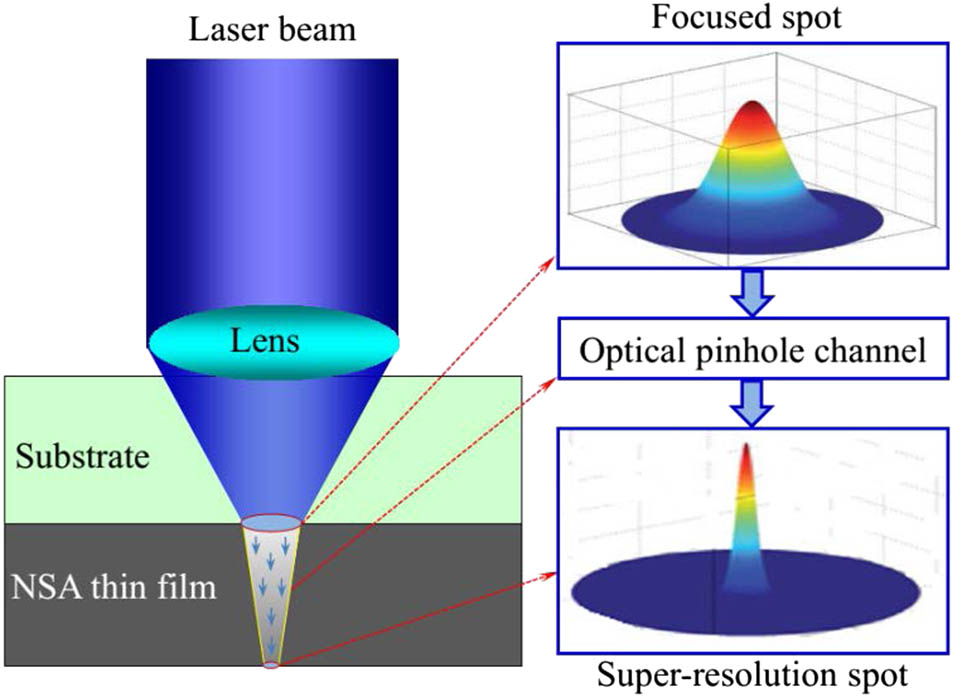
Fig. 1. Schematic of the NSA-induced superresolution spot effect.
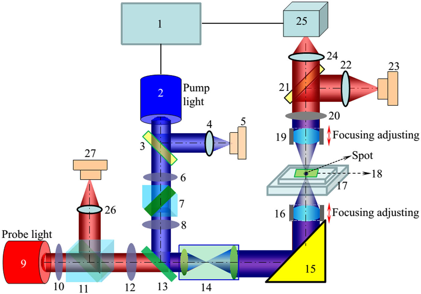
Fig. 2. Experimental setup. 1, signal generator; 2, BVL; 3, splitter (9 ∶ 1 5 ∶ 5
Fig. 3. Reversible characteristics of the optical pinhole channel.
Fig. 4. Time response of a single pump-pulse-induced optical pinhole channel (pump pulse width of 80 ns, power of 20 mW).
Fig. 5. Transmitted transient probe spots at delay times of (a) 0, (b) 60, (c) 80, (d) 120, and (e) 200 ns, respectively corresponding to letters A, B, C, D, and E in Fig. 4 .
Fig. 6. Transient superresolution probe spot. (a) The initial transient spot without the pump pulse excitation, (b) the transient superresolution spot captured at a delay time of 40 ns after the pump pulse excitation, (c) the comparison of the normalized intensity profiles of (a) and (b).

Set citation alerts for the article
Please enter your email address
© Copyright 2018-2021 | Chinese Laser Press. All Rights Reserved 沪ICP备15018463号-20