Author Affiliations
1MOE Key Laboratory for Nonequilibrium Synthesis and Modulation of Condensed Matter, Shaanxi Province Key Laboratory of Quantum Information and Quantum Optoelectronic Devices, School of Physics, Xi’an Jiaotong University, Xi’an 710049, China2State Key Laboratory of Transient Optics and Photonics, Xi’an Institute of Optics and Precision Mechanics, Chinese Academy of Sciences, Xi’an 710119, China3e-mail: yaobl@opt.ac.cnshow less
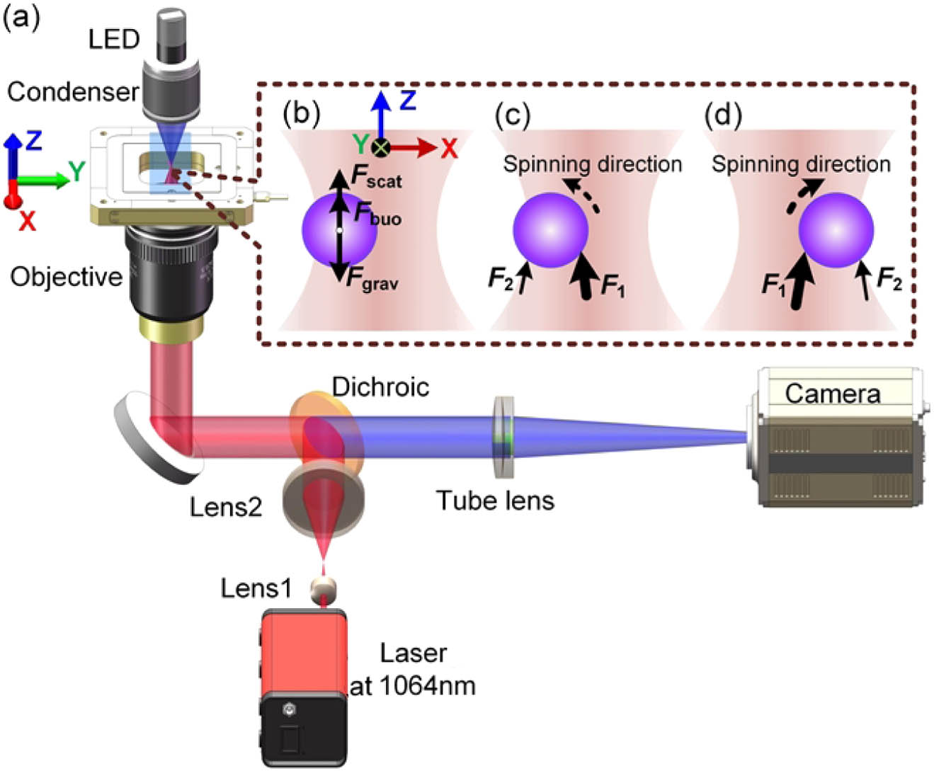
Fig. 1. Principle of the off-axis levitation and the transverse spinning of metallic microparticles. (a) Sketch for an inverted optical tweezers setup. (b) The principle of off-axis optical levitation of metallic microparticles. The scattering force along the z axis is balanced by the sum of the particle’s gravity and buoyancy. (c), (d) The principle of transverse spinning of optically confined metallic microparticles. The asymmetric force exerted on the particle will drive the particle to spin transversely. F1 and F2 denote the scattering force that the particles experience at the regions closer to and farther away from the beam axis, respectively. The thickness of the arrows denotes the magnitude of the force. Fscat, scattering force; Fbuo, buoyancy force; Fgrav, gravity.
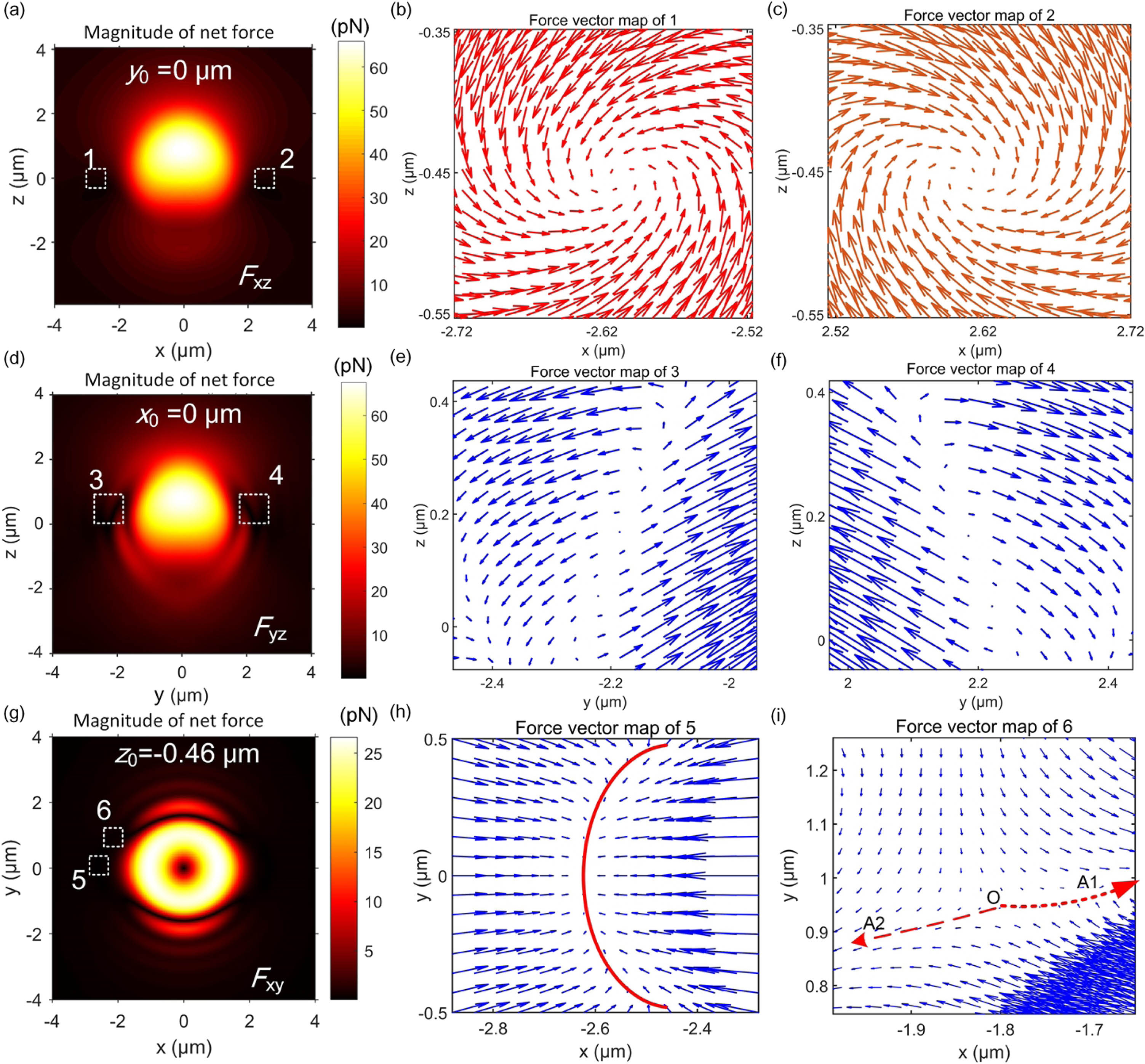
Fig. 2. Simulated force fields acting on a gold particle with a radius of 1.5 μm trapped in water with trapping power of 10 mW. (a) Spatial distribution of the magnitude of the 2D net force Fxz on the particle in the x−z plane at y0=0 μm. (b), (c) Two-dimensional vector maps of net force in regions 1 and 2 indicated by dashed white squares in part (a). (d) Spatial distribution of the magnitude of the 2D net force Fyz on the particle in the y−z plane at x0=0 μm. (e), (f) Two-dimensional vector maps of net force in regions 3 and 4 indicated by dashed white squares in part (d). (g) Spatial distribution of the magnitude of the 2D net force Fxy on the particle in the x−y plane at z0=−0.46 μm. (h), (i) Two-dimensional vector maps of net force in regions 5 and 6 indicated by dashed white squares in part (g). The red line in (h) denotes the possible positions for confining the gold particle. Point O in (i) denotes the unstable zero-force position. Arrows A1 and A2 indicate the possible directions that the particle will be pushed to. The 2D quantity Fij satisfies the relation Fij=(Fi2+Fj2)0.5, where Fi and Fj denote the forces pointing to the i and j axes (i,j=x,y, or z).
Fig. 3. The net forces experienced by a gold particle with a radius R=1.5 μm confined by a Gaussian beam with trapping power of 10 mW in the vicinity of the position (x0,y0,z0)=(−2.62,0,−0.46) μm. (a)–(c) The forces along the (a) z, (b) x, and (c) y axes at the positions (x0,y0)=(−2.62,0) μm, (y0,z0)=(0,−0.46) μm, and (x0,z0)=(−2.62,−0.46) μm, respectively. The inset in part (b) shows the force along the x axis in a smaller range.
Fig. 4. Experimental results of off-axis 3D optical confinement and manipulation of gold microparticles with the radius R≈1.5 μm (see Visualization 1). The sample stage moves along (a) the x direction, (b) the y direction, (c) the z direction, and (d) the x direction again after it is moved along the z direction over a distance of 10 μm. The output laser power is 1 W. Black arrows, the moving direction of sample stage; white triangles, the reference objects fixed on the surface of the sample chamber; white dots, positions of the Gaussian beam center; yellow dashed circles, the possible trapping positions at the edge of the focal spot; p1 and p2, the equilibrium positions. Scale bar: 5 μm.
Fig. 5. Equilibrium positions of the off-axis confined gold microparticle for various laser power (see Visualization 2). (a) The simulated and experimentally measured lateral displacement x0 from the focal spot center to the equilibrium position for various trapping power. (b) The simulated axial displacement z0 from the focal spot center to the equilibrium position for various power. (c) Off-axis confinement of a gold particle with R≈1.5 μm for the laser power of 10, 50, 100, 200, 500, and 1000 mW, respectively. Scale bar: 5 μm. Yellow crosses denote the location of the trapped particle center. Δr denotes the distance between the particle center and the focal spot center.
Fig. 6. Transverse spinning of gold microparticle assembly using a linearly polarized Gaussian beam (see Visualization 4). (a)–(f) Time-lapse images of transverse spinning of the particle assembly extracted from the video. Scale bar: 5 μm. p1 and p2, the trapping positions.