• Photonics Research
  • Vol. 9, Issue 11, 2144 (2021)
Yansheng Liang1, Shaohui Yan2, Zhaojun Wang1, Baoli Yao2、3, and Ming Lei1、*
Author Affiliations
  • 1MOE Key Laboratory for Nonequilibrium Synthesis and Modulation of Condensed Matter, Shaanxi Province Key Laboratory of Quantum Information and Quantum Optoelectronic Devices, School of Physics, Xi’an Jiaotong University, Xi’an 710049, China
  • 2State Key Laboratory of Transient Optics and Photonics, Xi’an Institute of Optics and Precision Mechanics, Chinese Academy of Sciences, Xi’an 710119, China
  • 3e-mail: yaobl@opt.ac.cn
  • show less
    DOI: 10.1364/PRJ.431413 Cite this Article Set citation alerts
    Yansheng Liang, Shaohui Yan, Zhaojun Wang, Baoli Yao, Ming Lei. Off-axis optical levitation and transverse spinning of metallic microparticles[J]. Photonics Research, 2021, 9(11): 2144 Copy Citation Text show less

    Abstract

    Optical manipulation of metallic microparticles remains a significant challenge because of the strong scattering forces arising from the high extinction coefficient of the particles. This paper reports a new mechanism for stable confinement of metallic microparticles using a tightly focused linearly polarized Gaussian beam. Theoretical and experimental results demonstrate that metallic microparticles can be captured off the optical axis in such a beam. Meanwhile, the three-dimensionally confined particles are observed spinning transversely as a response to the asymmetric force field. The off-axis levitation and transverse spinning of metallic microparticles may provide a new way for effective manipulation of metallic microparticles.

    1. INTRODUCTION

    Metallic particles are drawing increasing attention for their size- and shape-dependent optical properties [1], which have made them very effective tools in various applications, acting, for example, as drug carriers in drug delivery [2], label-free biosensors in biosensing [3], and optical nano-antennas in optical communications [4]. They have also been exploited as remotely, optically controlled micro/nanoscopic sources of heat for bubble formation [5], surface ejection [6], and cancer therapy [7]. Among these applications, efficient manipulation of metallic particles is of essential importance. Optical tweezers, a technique that uses focused light to manipulate microparticles, provide an elegant means.

    Compared with dielectric nanoparticles, metallic nanoparticles in the Rayleigh size regime are better candidates for optical trapping due to their higher polarizability [8,9]. Numerous theoretical and experimental works during the past two decades have shown that metallic nanoparticles exhibit higher trapping efficiency than their dielectric counterparts due to much larger gradient force while experiencing negligible scattering force [1015]. However, as the particles’ size increases, the scattering force increases dramatically due to their high extinction coefficient, making large-size metallic particles hard to trap. Theoretical work has been carried out to find the solutions to stable three-dimensional (3D) trapping of such particles [1620]. Early research revealed that Gaussian beam could provide stable two-dimensional trapping of gold Mie particles in the transverse plane [16,17]. Further simulations by Gu et al. showed that the trapping efficiency of metallic Mie particles could be enhanced by using a centrally obstructed Gaussian beam [18,19]. Despite theoretical predictions, the experimental demonstration of stable 3D trapping of metallic microparticles (diameter ≥ wavelength) with focused Gaussian beams is still an ongoing task [20]. Alternatively, a structured hollow trap, that is to say, a vortex beam trap, can be employed to confine a metallic microparticle [21,22]. Such a trap can push a metallic particle inward due to scattering forces, confining the particle to its dark center. The main drawback of using a structured hollow trap is that the longitudinal confinement is achieved by canceling the longitudinal scattering force with gravity. Therefore, a slight increase in trapping power would push the particle away from the trap.

    This paper reports a new mechanism of stable 3D confinement of metallic (gold) microparticles using a linearly polarized Gaussian beam. Numerical calculations show that the metallic (gold) microparticle can be stably confined at two off-axis positions in the vicinity of the focal plane by the vortex-like force field. This confinement is different from the optical levitation on the optical axis as reported previously [20]. Furthermore, the off-axis levitated gold microparticle will execute transverse spinning due to the torque arising from the asymmetric force field. Generally, optical spinning/rotation of particles requires unique properties of the illuminated particle, e.g.,  shape [23], birefringence [24], or specially structured illuminating beam, e.g.,  a circularly polarized beam [25,26] or a vortex beam [27,28]. The transverse spinning of metallic particles is intrinsically different from optical spinning utilizing the transfer of photon spin or orbital angular momentum [24,25,27,29], or based on the specially designed shape of the trapped particle [23], as it is induced by the vortex-like force field. Experimental results show a good agreement with the theoretical predictions: the gold microparticles were observed to be confined at two off-axis positions symmetric about the trap center and to spin transversely at a frequency of 6  Hz. Such asymmetric-field-dependent off-axis transverse spinning of metallic particles has never been reported before. It may serve as a new kind of optically driven rotator applied to experimental studies in biology or hydrodynamics [30].

    2. METHODS AND MATERIALS

    The experiment was conducted with an inverted optical tweezers setup as illustrated in Fig. 1(a). A collimated Gaussian beam polarized along the y axis with a wavelength of 1.064 μm was expanded by a telescope formed by lenses 1 and 2, directed into a high-numerical-aperture oil-immersion objective (100×/NA1.45, Nikon Inc., Japan) by a dichroic mirror and focused into a diffraction-limited spot to create the optical trap. The overall transmission of the system from the laser output to the focal plane was 25%. A CMOS camera (GS3-U3-41C6M-C, Point Grey Research Inc., USA, 90 fps at full resolution) with a resolution of 2048×2040 pixels, and pixel pitch of 5.5 μm was employed to monitor and record the manipulation process. An LED light source focused by a condenser was used to illuminate the samples for direct wide-field imaging. Gold particles (Thermo Fisher Scientific Inc., USA) with a diameter ranging from 1.0 to 5.0 μm and a density of 19.32  g/cm3 immersed in water (density 1.00  g/cm3, refractive index 1.33) were used as metallic probes. Typically the particles were confined at a distance of 5–10 μm from the sample chamber surface.

    Principle of the off-axis levitation and the transverse spinning of metallic microparticles. (a) Sketch for an inverted optical tweezers setup. (b) The principle of off-axis optical levitation of metallic microparticles. The scattering force along the z axis is balanced by the sum of the particle’s gravity and buoyancy. (c), (d) The principle of transverse spinning of optically confined metallic microparticles. The asymmetric force exerted on the particle will drive the particle to spin transversely. F1 and F2 denote the scattering force that the particles experience at the regions closer to and farther away from the beam axis, respectively. The thickness of the arrows denotes the magnitude of the force. Fscat, scattering force; Fbuo, buoyancy force; Fgrav, gravity.

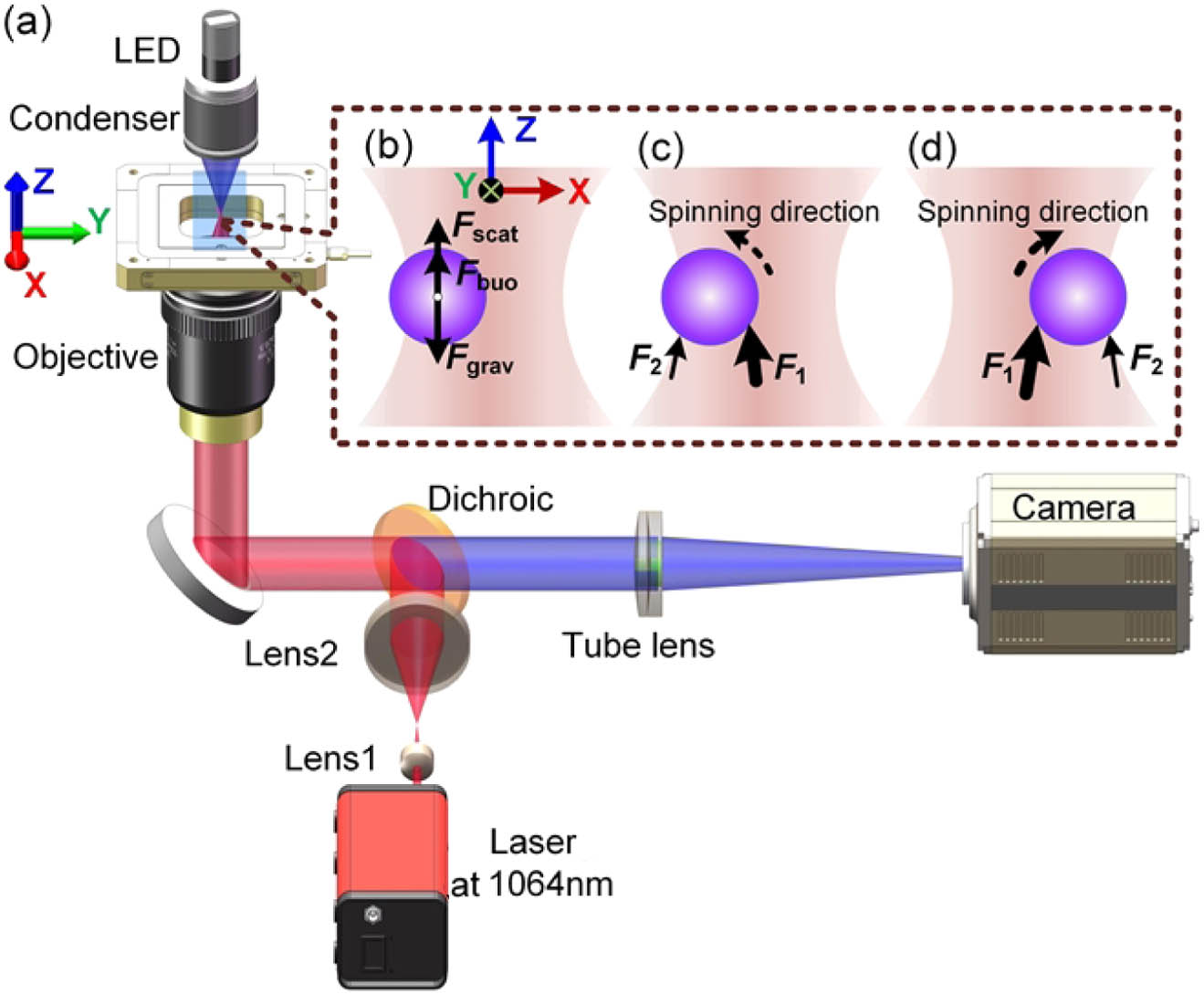
    Figure 1.Principle of the off-axis levitation and the transverse spinning of metallic microparticles. (a) Sketch for an inverted optical tweezers setup. (b) The principle of off-axis optical levitation of metallic microparticles. The scattering force along the z axis is balanced by the sum of the particle’s gravity and buoyancy. (c), (d) The principle of transverse spinning of optically confined metallic microparticles. The asymmetric force exerted on the particle will drive the particle to spin transversely. F1 and F2 denote the scattering force that the particles experience at the regions closer to and farther away from the beam axis, respectively. The thickness of the arrows denotes the magnitude of the force. Fscat, scattering force; Fbuo, buoyancy force; Fgrav, gravity.

    Figures 1(b)–1(d) present the principle of off-axis optical trapping and transverse spinning of metallic microparticles using a Gaussian trap. For large-size metallic particles, scattering force dominates and tends to push the particle out of the beam’s center, prohibiting on-axis trapping. However, a careful examination shows that off-axis confinement at the edge of the focal region is possible when considering a joint action of several mechanisms as shown in Fig. 1(b). At this position, the axial scattering force is balanced by the particle’s gravity (reduced by buoyancy), while the transverse scattering force is negligibly small so that the transverse gradient force can overcome the repelling effect. When departing this position, the particle will be pulled back by a restoring force [provided by a vortex-like force field shown in Figs. 2(b) and 2(c)] as discussed below. In such an asymmetric force field, the off-axis confined particle will spin about the transverse y axis with the sense of spinning depending on the force field as illustrated in Figs. 1(c) and 1(d). Specifically, the scattering force F1 acting on the particle at the particle side closer to the beam axis will be greater than the scattering force F2 acting on the opposite particle side, causing the particle to spin about the y axis. Note that gravity will cancel the net scattering force, while contributing zero torque about the particle center. Therefore, from the side view shown in Figs. 1(c) and 1(d), the particle spins anticlockwise in Fig. 1(c) and clockwise in Fig. 1(d).

    Simulated force fields acting on a gold particle with a radius of 1.5 μm trapped in water with trapping power of 10 mW. (a) Spatial distribution of the magnitude of the 2D net force Fxz on the particle in the x−z plane at y0=0 μm. (b), (c) Two-dimensional vector maps of net force in regions 1 and 2 indicated by dashed white squares in part (a). (d) Spatial distribution of the magnitude of the 2D net force Fyz on the particle in the y−z plane at x0=0 μm. (e), (f) Two-dimensional vector maps of net force in regions 3 and 4 indicated by dashed white squares in part (d). (g) Spatial distribution of the magnitude of the 2D net force Fxy on the particle in the x−y plane at z0=−0.46 μm. (h), (i) Two-dimensional vector maps of net force in regions 5 and 6 indicated by dashed white squares in part (g). The red line in (h) denotes the possible positions for confining the gold particle. Point O in (i) denotes the unstable zero-force position. Arrows A1 and A2 indicate the possible directions that the particle will be pushed to. The 2D quantity Fij satisfies the relation Fij=(Fi2+Fj2)0.5, where Fi and Fj denote the forces pointing to the i and j axes (i,j=x,y, or z).

    Figure 2.Simulated force fields acting on a gold particle with a radius of 1.5 μm trapped in water with trapping power of 10 mW. (a) Spatial distribution of the magnitude of the 2D net force Fxz on the particle in the xz plane at y0=0  μm. (b), (c) Two-dimensional vector maps of net force in regions 1 and 2 indicated by dashed white squares in part (a). (d) Spatial distribution of the magnitude of the 2D net force Fyz on the particle in the yz plane at x0=0  μm. (e), (f) Two-dimensional vector maps of net force in regions 3 and 4 indicated by dashed white squares in part (d). (g) Spatial distribution of the magnitude of the 2D net force Fxy on the particle in the xy plane at z0=0.46  μm. (h), (i) Two-dimensional vector maps of net force in regions 5 and 6 indicated by dashed white squares in part (g). The red line in (h) denotes the possible positions for confining the gold particle. Point O in (i) denotes the unstable zero-force position. Arrows A1 and A2 indicate the possible directions that the particle will be pushed to. The 2D quantity Fij satisfies the relation Fij=(Fi2+Fj2)0.5, where Fi and Fj denote the forces pointing to the i and j axes (i,j=x,y, or z).

    In simulations, the time-averaged optical force F exerted on a homogenous, isotropic spherical particle can be obtained by integrating the electromagnetic momentum flux over a spherical surface centered at the particle and located at infinity [18,31]: F=14limrr2Ω(εE2+μH2)ndΩ.Here, the angle bracket · denotes a time average, r is the radius of the spherical surface of integration, dΩ is the elemental solid angle, n is the unit radial vector; ε and μ are the electric permittivity and the magnetic permeability of the medium surrounding the particle, respectively. E=Einc+Esca is the total electric field, and likewise for the total magnetic field H. According to the T-matrix method, the incident field Einc and the scattered field Esca are respectively expressed in terms of vector spherical wave functions [3236]: Einc(r)=n=1m=nn[amnMmn1(kr)+bmnNmn1(kr)],Esca(r)=n=1m=nn[emnMmn3(kr)+fmnNmn3(kr)].Here Mmn1,3(kr) and Nmn1,3(kr) are vector spherical wave functions of the first and the third kinds. (amn,bmn) and (emn,fmn) are the expansion coefficients of the incident and the scattered fields, respectively, satisfying the following relation [3234]: [emnfmn]=[Tmnmn11Tmnmn12Tmnmn21Tmnmn22][amnbmn].Here T is called the T-matrix. Given an incident field Einc, the scattered field Esca and then the force can be precisely calculated via the T-matrix method and Eq. (1).

    3. RESULTS AND DISCUSSION

    A. Simulation Results

    The total optical force on the particle was computed via the integral in Eq. (1), where the incident focused fields were calculated with Richards–Wolf integral [37,38], and the scattered fields were calculated based on Eqs. (3) and (4) by using the T-matrix method [36,39]. Gold microparticles, with a dielectric constant ε=54+5.0i at 1064 nm [40], were used as samples. Throughout the simulations, the trap was assumed to be the focused field of a y-polarized Gaussian beam propagating along the z axis, and the numerical aperture (NA) of the lens was set to 1.32. In simulations, the power value refers to the power at the focal plane, while in experiment it refers to the output power of the laser. The origin of the coordinate system was located on the beam propagation axis in the beam focal plane. The gravity of the gold microspheres can be calculated by the formula ρgoldVgoldg, with Vgold denoting the volume of the particle and g=9.8  m/s2 denoting the gravitational constant. The buoyancy is calculated by the formula ρwaterVgoldg, with ρwater=1.0  g/cm3 denoting the density of water.

    To demonstrate the existence of off-axis equilibrium positions, we calculated the two-dimensional (2D) force distributions in the xz,yz, and xy planes experienced by a gold particle with a radius R=1.5  μm (Fig. 2). The net force fields took into account the particle’s gravity, the buoyancy force on the particle, and the optical force acting on the particle in the trap. The illumination power P was set to 10 mW. Figures 2(a) and 2(d) clearly show that the particle will fail to be trapped on the z axis, i.e., the beam axis, because of nonzero net force there, under the chosen illumination power. Note that by decreasing the power to an appropriate value, optical levitation on the z axis can be realized by taking into account particle gravity [20].

    Interestingly, however, there are two equilibrium positions (locations of zero net forces) at (x0,z0)=(±2.62,0.46)  μm in regions 1 and 2 in the xz plane. Moreover, the force vector maps in each of these regions present spiral vortex-like structures with mutually opposite circulation directions [Figs. 2(b) and 2(c)]. As a result, the gold particle is expected to be trapped at these zero force positions with spiral force distribution in the vicinity. Similarly, the zero-force positions are found in regions 3 and 4 of the yz plane. However, these zero-force positions are not stable, and consequently the particles will fail to be confined there [Figs. 2(e) and 2(f)]. The stable off-axis equilibrium positions are located in the plane perpendicular to the beam polarization for the linear polarization, e.g.,  the xz plane for the y polarization. To better understand the particle’s behavior, we further calculated the transverse force field in the xy plane at z0=0.46  μm. The results are shown in Figs. 2(g)–2(i). Figure 2(g) presents the xy plane map of the force magnitude, with the force vector maps of regions 5 and 6 shown in Figs. 2(h) and 2(i). Region 5 denotes the vicinity of the stable equilibrium position in the xz plane, and region 6 denotes the vicinity of an unstable zero-force point located nearby the stable equilibrium position. Figure 2(h) shows that the force vectors in the immediate neighborhood of the stable equilibrium position point to the equilibrium position. While multiple particles are positioned in this region, they will be arranged along the red curved line. Particles in region 6 will be either pushed along the direction denoted by A2 or A1 [Fig. 2(i)]. While they are moved to the A2 direction, they will be finally arranged along the red line shown in Fig. 2(h). In contrast, particles pushed to the A1 direction will be driven away from the beam, as there is no equilibrium position in the yz plane.

    To judge whether the above zero force positions, i.e., (x0,y0,z0)=(±2.62,0,0.46)  μm, are three-dimensional equilibrium positions, we calculated the forces along the x, y, and z axes around these positions. Figures 3(a)–3(c) present the force profiles along the x, y, and z axes passing through (x0,y0,z0)=(2.62,0,0.46)  μm calculated with the same settings as in Fig. 2. The results show that both the axial [Fig. 3(a)] and transverse [Figs. 3(b) and 3(c)] forces in the vicinity of the equilibrium position exhibit a restoring effect (negative slope) with the maximal forces 1.9  pN in the z direction, 0.3  pN in the x direction, and 0.5  pN in the y direction. In general, fractional pN force is large enough to defeat the Brownian motion to keep the particle stable in the trap.

    The net forces experienced by a gold particle with a radius R=1.5 μm confined by a Gaussian beam with trapping power of 10 mW in the vicinity of the position (x0,y0,z0)=(−2.62,0,−0.46) μm. (a)–(c) The forces along the (a) z, (b) x, and (c) y axes at the positions (x0,y0)=(−2.62,0) μm, (y0,z0)=(0,−0.46) μm, and (x0,z0)=(−2.62,−0.46) μm, respectively. The inset in part (b) shows the force along the x axis in a smaller range.

    Figure 3.The net forces experienced by a gold particle with a radius R=1.5  μm confined by a Gaussian beam with trapping power of 10 mW in the vicinity of the position (x0,y0,z0)=(2.62,0,0.46)  μm. (a)–(c) The forces along the (a) z, (b) x, and (c) y axes at the positions (x0,y0)=(2.62,0)  μm, (y0,z0)=(0,0.46)  μm, and (x0,z0)=(2.62,0.46)  μm, respectively. The inset in part (b) shows the force along the x axis in a smaller range.

    The off-axis levitated metallic particle tends to be more stable than the on-axis levitated one that can easily escape from the trap in the following sense. When the illumination power is changed, stable off-axis confinement still exists, although its position will change. For example, for the power P=10,50, and 100 mW, the simulation results show that the equilibrium positions (x0,z0) are (±2.62,0.46), (±3.75,0.24), and (±4.33,0.18)  μm, respectively. The equilibrium positions are found to move away from the beam’s center with increased power. In contrast, the on-axis optically levitated metallic particle would be repelled from the trap if the power increases significantly. The appropriate power range for on-axis levitation is quite small. For instance, for gold particles with R=1.5  μm immersed in water and NA=1.32, the power range is about [1.83, 1.93] mW according to our simulations.

    In addition to stable confinement, another appealing property of off-axis levitation is the vortex-like force field experienced by the particle as demonstrated in Fig. 2. When being confined at the stable equilibrium positions, the particle is expected to execute a transverse spinning motion. The calculated spin torque on the particle with R=1.5  μm at the equilibrium position over x>0 region confirms this prediction [41]. For P=100  mW, the spin torque components Γx,Γy, and Γz are 7.92×10¹⁷, 3.94, and 2.21×10¹⁶  pN·μm, respectively. Thus, the spin torque is predominantly along the y direction, causing the particle to spin around the y-axis.

    B. Experimental Results

    1. Off-axis Levitation

    The above numerical results predict that a gold microparticle will be stably confined at two edge positions of a focused Gaussian beam spot. Figure 4 presents the time-lapse images of two gold microparticles (R1.5  μm) subject to the trap, from which we can find that the particles are stably confined at two edge sides (p1 and p2) of the focal spot (marked by a white dot). When the sample stage moved along the x direction, the two particles remained stably confined near the trap edge indicated by the dashed ring as shown in Fig. 4(a). In particular, when the particle deviated from its equilibrium position due to a disturbance, say, a rapid movement of the stage [see the particle at the position of p2 in the third frame of Fig. 4(a)], the restoring force would pull the particle back to the original position [see the fourth frame of Fig. 4(a)]. When the sample stage moved to the left along the y direction, the two particles remained stably trapped, but the equilibrium positions shifted slightly to the left relative to those at rest [Fig. 4(b)]. This may be caused by the friction of fluid. To verify the 3D stable trapping, we translated the sample stage along the z direction so that the distance between the confined particles and the sample chamber surface was increasing [Fig. 4(c)]. The two particles were seen to stay in the trap during the movement. Since we used a high-NA oil immersion objective, changes of focusing distance from the sample chamber surface led to changes in the trapping beam profile due to spherical aberrations. This is most likely why the particles move out of the focal plane and away from the dashed yellow circle during the z axis translation. Following the translation of the stage by 10 μm along the z direction, the stage was again translated along the x direction [see Fig. 4(d)]. Still, the two particles were stably held in the trap. In summary, Fig. 4 demonstrates an off-axis 3D stable confinement of metallic microparticles by using a Gaussian beam (see also Visualization 1).

    Experimental results of off-axis 3D optical confinement and manipulation of gold microparticles with the radius R≈1.5 μm (see Visualization 1). The sample stage moves along (a) the x direction, (b) the y direction, (c) the z direction, and (d) the x direction again after it is moved along the z direction over a distance of 10 μm. The output laser power is 1 W. Black arrows, the moving direction of sample stage; white triangles, the reference objects fixed on the surface of the sample chamber; white dots, positions of the Gaussian beam center; yellow dashed circles, the possible trapping positions at the edge of the focal spot; p1 and p2, the equilibrium positions. Scale bar: 5 μm.

    Figure 4.Experimental results of off-axis 3D optical confinement and manipulation of gold microparticles with the radius R1.5  μm (see Visualization 1). The sample stage moves along (a) the x direction, (b) the y direction, (c) the z direction, and (d) the x direction again after it is moved along the z direction over a distance of 10 μm. The output laser power is 1 W. Black arrows, the moving direction of sample stage; white triangles, the reference objects fixed on the surface of the sample chamber; white dots, positions of the Gaussian beam center; yellow dashed circles, the possible trapping positions at the edge of the focal spot; p1 and p2, the equilibrium positions. Scale bar: 5 μm.

    Equilibrium positions of the off-axis confined gold microparticle for various laser power (see Visualization 2). (a) The simulated and experimentally measured lateral displacement x0 from the focal spot center to the equilibrium position for various trapping power. (b) The simulated axial displacement z0 from the focal spot center to the equilibrium position for various power. (c) Off-axis confinement of a gold particle with R≈1.5 μm for the laser power of 10, 50, 100, 200, 500, and 1000 mW, respectively. Scale bar: 5 μm. Yellow crosses denote the location of the trapped particle center. Δr denotes the distance between the particle center and the focal spot center.

    Figure 5.Equilibrium positions of the off-axis confined gold microparticle for various laser power (see Visualization 2). (a) The simulated and experimentally measured lateral displacement x0 from the focal spot center to the equilibrium position for various trapping power. (b) The simulated axial displacement z0 from the focal spot center to the equilibrium position for various power. (c) Off-axis confinement of a gold particle with R1.5  μm for the laser power of 10, 50, 100, 200, 500, and 1000 mW, respectively. Scale bar: 5 μm. Yellow crosses denote the location of the trapped particle center. Δr denotes the distance between the particle center and the focal spot center.

    As predicted by the above simulations, the off-axis levitated metallic particles are more stable than the on-axis levitated ones concerning changes in the trapping power. To validate this, we investigated the behavior of the off-axis confined particle under different laser power (Fig. 5). Figure 5(a) shows that the lateral displacement x0 from the focal spot center to the equilibrium position increases with power. Note that the curve of the dependence of x0 on power gets less steep for increasing values of power. The trend shows that, under high-power illumination, the particle will be confined at the very edge of the focal spot, where the intensity remains almost unchanged. Moreover, the axial position z0 increases with increasing power, as the value of z0 becomes less negative, meaning that the particle gets closer to the focal plane [Fig. 5(b)]. The change of the equilibrium positions along the lateral and axial directions is caused by the changing axial scattering force. When increasing the laser power, the scattering force will increase accordingly. Therefore, the axial equilibrium position will change accordingly, leading to the change of the lateral equilibrium position. At the new equilibrium position, the longitudinal scattering force still dominates and is balanced by the particle gravity. Note that for the power larger than about 200 mW, the value of z0 remains nearly unchanged.

    The trend shown in Figs. 5(a) and 5(b) indicates that there is no high-power limit on the trapping stability. Therefore the off-axis levitated particle has higher trapping stability than the on-axis levitated one [20]. The low-power limit is given by the requirement that the scattering force is large enough to cancel the gravity of the particle and defeat the Brownian motion as well. The experimental results confirm the particle’s behavior under different illumination power [Fig. 5(c) and Visualization 2]. When P was 10  mW, the gold particle stayed near the center of the focal spot [white dot, Fig. 5(c1)]. While gradually increasing the output power, the particle still remained stably trapped, but with equilibrium position moving away from the focal spot center [Figs. 5(c1)–5(c6)]. For the output power of 10, 50, 100, 200, 500, and 1000 mW, the lateral displacements are approximately 1.92, 2.86, 3.19, 3.67, 4.52, and 5.74 μm, respectively. Converting the output laser powers to the powers in the focal region, which are 2.5, 12.5, 25, 50, 125, and 250 mW, respectively, we find that the experimental results are well consistent with the theoretical predictions [Fig. 5(a)]. However, in the case of on-axis levitation, the metallic particle would be kicked out of the trap due to high scattering force under high trapping power.

    Transverse spinning of gold microparticle assembly using a linearly polarized Gaussian beam (see Visualization 4). (a)–(f) Time-lapse images of transverse spinning of the particle assembly extracted from the video. Scale bar: 5 μm. p1 and p2, the trapping positions.

    Figure 6.Transverse spinning of gold microparticle assembly using a linearly polarized Gaussian beam (see Visualization 4). (a)–(f) Time-lapse images of transverse spinning of the particle assembly extracted from the video. Scale bar: 5 μm. p1 and p2, the trapping positions.

    2. Off-Axis Transverse Spinning

    Besides trapping, the spinning of particles also attracts wide attention because of its wide applications and the interesting physics behind it. Compared to longitudinal spinning about the beam propagation direction, which has been widely investigated [42,43], transverse spinning of the particle about the axis perpendicular to the beam propagation direction is still at its infancy and will gain continually growing attention in the future. Our theoretical analysis has suggested a transverse spinning of an off-axis trapped gold particle due to the asymmetric force field, unlike that utilizing transfer of photon spin or orbital angular momentum or the particle’s shape. Experimental results indicate transverse spinning of a single quasi-spherical gold microparticle by the periodic motion (Visualization 3).

    However, although we can distinguish the spinning motion, it is difficult to determine the spinning rate. To provide clear spinning results, we selected an asymmetric particle assembly as the candidate, formed by two large (R4  μm) particles adhered to each other and several smaller (R1  μm) particles on the surface of the two large ones (Fig. 6). The particle assembly was confined at one of the two equilibrium positions labeled p2. The snapshots extracted from the time-lapse video provided in Visualization 4 show clear visualization of transverse spinning motion. The 3D models shown in the insets indicate the rotation state of the particles. In the beginning, the small particle marked by the yellow arrow lies on the right side of the assembly [Fig. 6(a)]. As time goes on, it appears to the front of the particle assembly [Fig. 6(b)] and then the left [Fig. 6(c)]. The motion of the small particle implies transverse spinning of the particle assembly about the transverse axis labeled by the yellow dashed arrow. Viewed from the lower-left corner, along the yellow dashed arrow, the spinning is anticlockwise. At t=60100  ms, the marked particle gradually disappears [Fig. 6(d)], and another particle moves up [Figs. 6(e) and 6(f)]. The spinning rate was measured as 6.3  Hz (see Visualization 4). When the particle assembly was trapped at the other equilibrium position labeled p1, it would transversely spin as well, but in the opposite direction (see Visualization 5). In this case, the spinning rate was 3.4  Hz. The difference in the spinning rates may be caused by the variations of the beam profile and the assembly’s shape. Note that the particle assemblies used for recording Visualization 4 and Visualization 5 were just a little different. Therefore, from the spinning motion and sense, we can conclude that the spinning should be induced by the vortex-like force field and not by the asymmetry of the particle assembly.

    By using a linearly polarized Gaussian beam, metallic particles were demonstrated to be confined at the two equilibrium positions shown in Fig. 4. When the particles are placed at other positions near these two equilibrium positions, they tend to be attracted to the equilibrium positions [Fig. 2(i)]. This feature can be exploited to assemble metallic microparticles along arcs centered at the equilibrium positions (see Visualization 6). While being confined near the equilibrium position, the particle is expected to do the circulatory motion about the location of zero force in a strongly non-conservative force field [44]. We observed that the particles with small size more easily undergwent the circulatory motion because their Brownian motion was more vital, making them always go away from the equilibrium position. When they get away from this position, the vortex-like force field drives them to rotate around this position.

    4. CONCLUSION

    In summary, we have reported and characterized a new mechanism for the optical manipulation of metallic (gold) microparticles. Specifically, we demonstrated the off-axis optical levitation of metallic microparticles using a linearly polarized Gaussian beam by theoretical analysis (Figs. 2 and 3) and experimental measurements (Figs. 4 and 5). The off-axis levitation of metallic microparticles is much more stable than the on-axis levitation [1820]. While being confined off the axis of the Gaussian beam, the metallic microparticle has been demonstrated to do transverse spinning simultaneously as a result of the asymmetric force field (Fig. 6). This transversely spinning metallic microparticle can serve as a new source of controllable micro-flow generation or a new kind of spanner.

    Moreover, although the gold particle has a large imaginary component of the dielectric constant, there seems no significant influence of the heating of the particle on the stable confinement. In the experiments, we have not observed the escape of the particles from the trap when confined in the trap for a few minutes. The change of the stable equilibrium positions results in the magnitude of intensity always being low enough to introduce heating effects, such as convection and bubble formation. We believe that the off-axis confinement of metallic particles will serve as a promising tool for many applications, for example, to construct dynamically tunable or reconfigurable metamaterials in material science [45].

    References

    [1] E. A. Coronado, E. R. Encina, F. D. Stefani. Optical properties of metallic nanoparticles: manipulating light, heat and forces at the nanoscale. Nanoscale, 3, 4042-4059(2011).

    [2] A. Saneja, J. Meena, A. Gupta, A. K. Panda, E. Lichtfouse, R. Ahuja, A. K. Panda, S. Bhaskar. Inorganic particles for delivering natural products. Sustainable Agriculture Reviews 44: Pharmaceutical Technology for Natural Products Delivery, 2, 205-241(2020).

    [3] S. K. Dondapati, T. K. Sau, C. Hrelescu, T. A. Klar, F. D. Stefani, J. Feldmann. Label-free biosensing based on single gold nanostars as plasmonic transducers. ACS Nano, 4, 6318-6322(2010).

    [4] P. Bharadwaj, B. Deutsch, L. Novotny. Optical antennas. Adv. Opt. Photon., 1, 438-483(2009).

    [5] V. Kotaidis, A. Plech. Cavitation dynamics on the nanoscale. Appl. Phys. Lett., 87, 213102(2005).

    [6] W. Huang, W. Qian, M. A. El-Sayed. Gold nanoparticles propulsion from surface fueled by absorption of femtosecond laser pulse at their surface plasmon resonance. J. Am. Chem. Soc., 128, 13330-13331(2006).

    [7] D. Jaque, L. M. Maestro, B. Del Rosal, P. Haro-Gonzalez, A. Benayas, J. Plaza, E. M. Rodriguez, J. G. Sole. Nanoparticles for photothermal therapies. Nanoscale, 6, 9494-9530(2014).

    [8] K. Svoboda, S. M. Block. Optical trapping of metallic Rayleigh particles. Opt. Lett., 19, 930-932(1994).

    [9] D. Gao, W. Ding, M. Nieto-Vesperinas, X. Ding, M. Rahman, T. Zhang, C. Lim, C.-W. Qiu. Optical manipulation from the microscale to the nanoscale: fundamentals, advances and prospects. Light Sci. Appl., 6, e17039(2017).

    [10] Q. Zhan. Trapping metallic Rayleigh particles with radial polarization. Opt. Express, 12, 3377-3382(2004).

    [11] P. M. Hansen, V. K. Bhatia, N. Harrit, L. Oddershede. Expanding the optical trapping range of gold nanoparticles. Nano Lett., 5, 1937-1942(2005).

    [12] J.-Q. Qin, X.-L. Wang, D. Jia, J. Chen, Y.-X. Fan, J. Ding, H.-T. Wang. FDTD approach to optical forces of tightly focused vector beams on metal particles. Opt. Express, 17, 8407-8416(2009).

    [13] F. Hajizadeh, S. N. S. Reihani. Optimized optical trapping of gold nanoparticles. Opt. Express, 18, 551-559(2010).

    [14] L. Huang, H. Guo, J. Li, L. Ling, B. Feng, Z.-Y. Li. Optical trapping of gold nanoparticles by cylindrical vector beam. Opt. Lett., 37, 1694-1696(2012).

    [15] L. Jauffred, S. M. Taheri, R. Schmitt, H. Linke, L. B. Oddershede. Optical trapping of gold nanoparticles in air. Nano Lett., 15, 4713-4719(2015).

    [16] H. Furukawa, I. Yamaguchi. Optical trapping of metallic particles by a fixed Gaussian beam. Opt. Lett., 23, 216-218(1998).

    [17] P. C. Ke, M. Gu. Characterization of trapping force on metallic Mie particles. Appl. Opt., 38, 160-167(1999).

    [18] M. Gu, D. Morrish, P. C. Ke. Enhancement of transverse trapping efficiency for a metallic particle using an obstructed laser beam. Appl. Phys. Lett., 77, 34-36(2000).

    [19] M. Gu, D. Morrish. Three-dimensional trapping of Mie metallic particles by the use of obstructed laser beams. J. Appl. Phys., 91, 1606-1612(2002).

    [20] Y. Zhang, X. Dou, Y. Dai, X. Wang, C. Min, X. Yuan. All-optical manipulation of micrometer-sized metallic particles. Photon. Res., 6, 66-71(2018).

    [21] K. Sakai, S. Noda. Optical trapping of metal particles in doughnut-shaped beam emitted by photonic-crystal laser. Electron. Lett., 43, 107-108(2007).

    [22] Z. Shen, L. Su, X. C. Yuan, Y. C. Shen. Trapping and rotating of a metallic particle trimer with optical vortex. Appl. Phys. Lett., 109, 241901(2016).

    [23] P. Galajda, P. Ormos. Rotors produced and driven in laser tweezers with reversed direction of rotation. Appl. Phys. Lett., 80, 4653-4655(2002).

    [24] R. L. Eriksen, P. J. Rodrigo, V. R. Daria, J. Glückstad. Spatial light modulator controlled alignment and spinning of birefringent particles optically trapped in an array. Appl. Opt., 42, 5107-5111(2003).

    [25] P. L. Marston, J. H. Crichton. Radiation torque on a sphere caused by a circularly-polarized electromagnetic wave. Phys. Rev. A, 30, 2508-2516(1984).

    [26] Y. Zhao, D. Shapiro, D. McGloin, D. T. Chiu, S. Marchesini. Direct observation of the transfer of orbital angular momentum to metal particles from a focused circularly polarized Gaussian beam. Opt. Express, 17, 23316-23322(2009).

    [27] L. Allen, M. W. Beijersbergen, R. J. C. Spreeuw, J. P. Woerdman. Orbital angular momentum of light and the transformation of Laguerre-Gaussian laser modes. Phys. Rev. A, 45, 8185-8189(1992).

    [28] A. T. O’Neil, M. J. Padgett. Three-dimensional optical confinement of micron-sized metal particles and the decoupling of the spin and orbital angular momentum within an optical spanner. Opt. Commun., 185, 139-143(2000).

    [29] N. B. Simpson, K. Dholakia, L. Allen, M. J. Padgett. Mechanical equivalence of spin and orbital angular momentum of light: an optical spanner. Opt. Lett., 22, 52-54(1997).

    [30] M. Padgett, R. Bowman. Tweezers with a twist. Nat. Photonics, 5, 343-348(2011).

    [31] P. H. Jones, O. M. Maragò, G. Volpe. Optical tweezers: Principles and Applications(2015).

    [32] P. C. Waterman. New formulation of acoustic scattering. J. Acoust. Soc. Am., 45, 1417-1429(1969).

    [33] P. C. Waterman. Symmetry, unitarity, and geometry in electromagnetic scattering. Phys. Rev. D, 3, 825-839(1971).

    [34] I. M. Michael, D. Larry. Scattering, Absorption and Emission of Light by Small Particles(2002).

    [35] S. Yan, B. Yao. Transverse trapping forces of focused Gaussian beam on ellipsoidal particles. J. Opt. Soc. Am. B, 24, 1596-1602(2007).

    [36] S. Yan, B. Yao. Radiation forces of a highly focused radially polarized beam on spherical particles. Phys. Rev. A, 76, 053836(2007).

    [37] E. Wolf. Electromagnetic diffraction in optical systems. I. An integral representation of the image field. Proc. R. Soc. London A, 253, 349-357(1959).

    [38] B. Richards, E. Wolf. Electromagnetic diffraction in optical systems. II. Structure of the image field in an aplanatic system. Proc. R. Soc. London A, 253, 358-379(1959).

    [39] T. A. Nieminen, H. Rubinsztein-Dunlop, N. R. Heckenberg, A. I. Bishop. Numerical modelling of optical trapping. Comput. Phys. Commun., 142, 468-471(2001).

    [40] S. Adachi. The Handbook on Optical Constants of Metals: In Tables and Figures(2012).

    [41] M. Li, S. Yan, B. Yao, Y. Liang, G. Han, P. Zhang. Optical trapping force and torque on spheroidal Rayleigh particles with arbitrary spatial orientations. J. Opt. Soc. Am. A, 33, 1341-1347(2016).

    [42] R. Reimann, M. Doderer, E. Hebestreit, R. Diehl, M. Frimmer, D. Windey, F. Tebbenjohanns, L. Novotny. GHz rotation of an optically trapped nanoparticle in vacuum. Phys. Rev. Lett., 121, 033602(2018).

    [43] J. Ahn, Z. Xu, J. Bang, Y.-H. Deng, T. M. Hoang, Q. Han, R.-M. Ma, T. Li. Optically levitated nanodumbbell torsion balance and GHz nanomechanical rotor. Phys. Rev. Lett., 121, 033603(2018).

    [44] G. Pesce, G. Volpe, A. C. D. Luca, G. Rusciano, G. Volpe. Quantitative assessment of non-conservative radiation forces in an optical trap. Europhys. Lett., 86, 38002(2009).

    [45] H. Gao, Y. Xu, K. Yao, Y. Liu. Self-assembly of silica–gold core–shell microparticles by electric fields toward dynamically tunable metamaterials. ACS Appl. Mater. Interfaces, 13, 14417-14422(2021).

    Yansheng Liang, Shaohui Yan, Zhaojun Wang, Baoli Yao, Ming Lei. Off-axis optical levitation and transverse spinning of metallic microparticles[J]. Photonics Research, 2021, 9(11): 2144
    Download Citation