• Photonics Research
  • Vol. 10, Issue 10, 2366 (2022)
Hanke Feng1、†, Ke Zhang1、†, Wenzhao Sun1, Yangming Ren2、3, Yiwen Zhang1, Wenfu Zhang2、3, and Cheng Wang1、*
Author Affiliations
  • 1Department of Electrical Engineering & State Key Laboratory of Terahertz and Millimeter Waves, City University of Hong Kong, Kowloon, Hong Kong, China
  • 2State Key Laboratory of Transient Optics and Photonics, Xi’an Institute of Optics and Precision Mechanics, Chinese Academy of Sciences, Xi’an 710119, China
  • 3University of Chinese Academy of Sciences, Beijing 100049, China
  • show less
    DOI: 10.1364/PRJ.464650 Cite this Article Set citation alerts
    Hanke Feng, Ke Zhang, Wenzhao Sun, Yangming Ren, Yiwen Zhang, Wenfu Zhang, Cheng Wang. Ultra-high-linearity integrated lithium niobate electro-optic modulators[J]. Photonics Research, 2022, 10(10): 2366 Copy Citation Text show less
    Schematic of the high-linearity RAMZI modulator. (a) False-color microscope image of the fabricated LN RAMZI modulator, where a racetrack resonator is overcoupled to the top path of an MZI via a 2×2 MMI coupler. Two pairs of ground-signal modulation electrodes are placed along the straight arms of the racetrack resonator to induce phase modulation. Two closely spaced RF signals (f1 and f2) are upconverted to optical frequencies (near fc) via the modulator. The RAMZI is designed to provide a linearized EO response and suppress the unwanted spurious harmonics (i.e., 2f1−f2 and 2f2−f1) in the output modulated optical signal. The right inset shows the cross section view of the modulation region. The left inset shows the SEM image of the waveguide bend region. (b)–(d) Working principle of the RAMZI modulator. The ring/racetrack resonator in deep overcoupling state functions as an all-pass filter near the off-resonance point (b), where the output phase response Δφring exhibits a super-linear relation with modulation phase Δφmod [red curve in (b)] while the intensity stays at unity level [blue curve in (b)]. (c) This super-linearity could be designed to compensate for the sub-linearity of the MZI at the quadrature point when the two arms combine, (d) therefore realizing a much-linearized Fano line shape in the full RAMZI device.
    Fig. 1. Schematic of the high-linearity RAMZI modulator. (a) False-color microscope image of the fabricated LN RAMZI modulator, where a racetrack resonator is overcoupled to the top path of an MZI via a 2×2 MMI coupler. Two pairs of ground-signal modulation electrodes are placed along the straight arms of the racetrack resonator to induce phase modulation. Two closely spaced RF signals (f1 and f2) are upconverted to optical frequencies (near fc) via the modulator. The RAMZI is designed to provide a linearized EO response and suppress the unwanted spurious harmonics (i.e., 2f1f2 and 2f2f1) in the output modulated optical signal. The right inset shows the cross section view of the modulation region. The left inset shows the SEM image of the waveguide bend region. (b)–(d) Working principle of the RAMZI modulator. The ring/racetrack resonator in deep overcoupling state functions as an all-pass filter near the off-resonance point (b), where the output phase response Δφring exhibits a super-linear relation with modulation phase Δφmod [red curve in (b)] while the intensity stays at unity level [blue curve in (b)]. (c) This super-linearity could be designed to compensate for the sub-linearity of the MZI at the quadrature point when the two arms combine, (d) therefore realizing a much-linearized Fano line shape in the full RAMZI device.
    Optical characterization of the RAMZI. (a) Measured optical transmission spectrum of the fabricated RAMZI device (blue solid curve), showing different line shapes depending on the phase difference Δφmzi of the unbalanced MZI (purple dashed line). Linearized Fano line shape could be observed at the quadrature points of the MZI (Δφmzi=π/2 or 3π/2), as shown in the insets. (b) Measured optical transmissions of the RAMZI modulator (red) and a reference MZI modulator (blue), as functions of applied voltages, showing a broadened linear regime in the RAMZI. The applied voltages are normalized by the respective half-wave voltages, Vπ, for easier comparison. (c) SEM image of the 2×2 MMI structure used for achieving the deep overcoupling state of the racetrack resonator. (d) Simulated electric field intensity evolution along the 2×2 MMI structure with a coupling coefficient of κ=0.96.
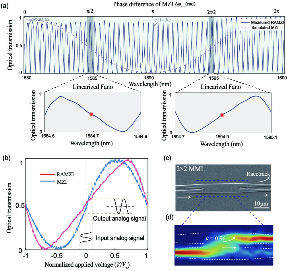
    Fig. 2. Optical characterization of the RAMZI. (a) Measured optical transmission spectrum of the fabricated RAMZI device (blue solid curve), showing different line shapes depending on the phase difference Δφmzi of the unbalanced MZI (purple dashed line). Linearized Fano line shape could be observed at the quadrature points of the MZI (Δφmzi=π/2 or 3π/2), as shown in the insets. (b) Measured optical transmissions of the RAMZI modulator (red) and a reference MZI modulator (blue), as functions of applied voltages, showing a broadened linear regime in the RAMZI. The applied voltages are normalized by the respective half-wave voltages, Vπ, for easier comparison. (c) SEM image of the 2×2 MMI structure used for achieving the deep overcoupling state of the racetrack resonator. (d) Simulated electric field intensity evolution along the 2×2 MMI structure with a coupling coefficient of κ=0.96.
    Linearity performance of the RAMZI modulator. (a) Experimental setup for SFDR measurements. The test link does not require an EDFA after modulation due to the high-power handling capability of LN, therefore minimizing the extra noise from EDFA when amplifying small signals. FPC, fiber polarization controller; DUT, device under test. (b),(c) Measured output FH and IMD3 powers versus input RF powers for the RAMZI (red) and the reference MZI (blue), showing high SFDR values of 120.04 dB·Hz4/5 and 114.54 dB·Hz4/5 at 1 GHz (b) and 5 GHz (c), respectively.
    Fig. 3. Linearity performance of the RAMZI modulator. (a) Experimental setup for SFDR measurements. The test link does not require an EDFA after modulation due to the high-power handling capability of LN, therefore minimizing the extra noise from EDFA when amplifying small signals. FPC, fiber polarization controller; DUT, device under test. (b),(c) Measured output FH and IMD3 powers versus input RF powers for the RAMZI (red) and the reference MZI (blue), showing high SFDR values of 120.04  dB·Hz4/5 and 114.54  dB·Hz4/5 at 1 GHz (b) and 5 GHz (c), respectively.
    Detuning and power dependence of the RAMZI modulator. (a), (b) Measured FH (red) and IMD3 (blue) powers at various detuning wavelengths within one FSR when the MZI is biased at (a) Δφmzi=π/2 and (b) Δφmzi=3π/2, at a fixed input RF power of 15 dBm. Strong suppression of the IMD3 products could be observed at the off-resonance points (B and E). (c) Measured SFDRs at 1 GHz as a function of the received optical powers, with a fitted slope of 1.59±0.02 in log-log scale. The highest SFDR is measured at a received power of 10 dBm, limited by the PD saturation power (black dash line). (d) Measured and simulated SFDRs at different RF frequencies (normalized by the resonator FSR) for the RAMZI and the reference MZI.
    Fig. 4. Detuning and power dependence of the RAMZI modulator. (a), (b) Measured FH (red) and IMD3 (blue) powers at various detuning wavelengths within one FSR when the MZI is biased at (a) Δφmzi=π/2 and (b) Δφmzi=3π/2, at a fixed input RF power of 15 dBm. Strong suppression of the IMD3 products could be observed at the off-resonance points (B and E). (c) Measured SFDRs at 1 GHz as a function of the received optical powers, with a fitted slope of 1.59±0.02 in log-log scale. The highest SFDR is measured at a received power of 10 dBm, limited by the PD saturation power (black dash line). (d) Measured and simulated SFDRs at different RF frequencies (normalized by the resonator FSR) for the RAMZI and the reference MZI.
    Simulated SFDR values as functions of modulation frequency for RAMZIs with different FSRs (solid lines), as well as MZI (green dashed line). The 170 GHz RAMZI shows nearly 10 dB improvement over MZI even at a high frequency of 26 GHz, covering the entire microwave K band.
    Fig. 5. Simulated SFDR values as functions of modulation frequency for RAMZIs with different FSRs (solid lines), as well as MZI (green dashed line). The 170 GHz RAMZI shows nearly 10 dB improvement over MZI even at a high frequency of 26 GHz, covering the entire microwave K band.
    Hanke Feng, Ke Zhang, Wenzhao Sun, Yangming Ren, Yiwen Zhang, Wenfu Zhang, Cheng Wang. Ultra-high-linearity integrated lithium niobate electro-optic modulators[J]. Photonics Research, 2022, 10(10): 2366
    Download Citation