
Zhitong Cui, Wei Chen, Yayun Dong, Xin Nie, Wei Wu, Zheng Liu. Circuit simulation of GJB151B CS115 part П: The analysis of application[J]. High Power Laser and Particle Beams, 2022, 34(6): 063003
- High Power Laser and Particle Beams
- Vol. 34, Issue 6, 063003 (2022)
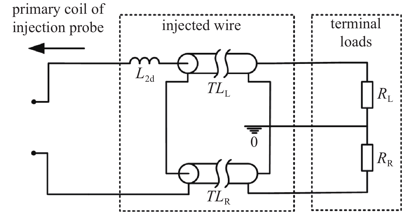
Fig. 1. Circuit model of CS115 injected on the single wire
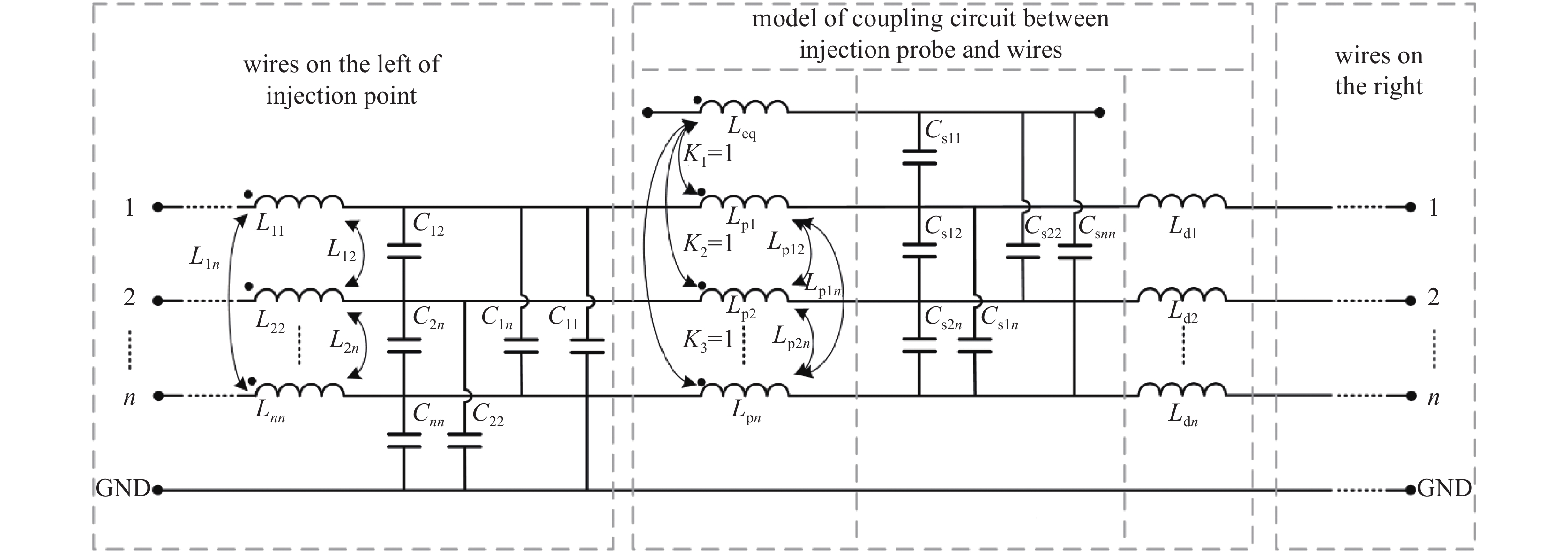
Fig. 2. Circuit model of CS115 injected on wire bundles
Fig. 3. Circuit model of CS115 injected on coaxial cable
Fig. 4. Simulated voltage across the terminal load (V TC)with different height of the wire
Fig. 5. Simulated voltage across the terminal load (V TC)with different length of the wire
Fig. 6. Simulated normalized voltage across the terminal load (V TC) with different values
Fig. 7. Simulated voltage across the terminal load (V TC)with different injected point of the wire
Fig. 8. Simulated normalized voltage across the terminal load (V TC) with different values of the series resistance between the impulse generator and injection probe
Fig. 9. Simulated voltage across the terminal load (V TC) with different number of wires
Fig. 10. Simulated voltage across the terminal load of the inner conductor (V TI) with different height of the coaxial cable
Fig. 11. Simulated voltage across the terminal load of the inner conductor (V TI) with different length of the coaxial cable
Fig. 12. Simulated voltage across the terminal load of the inner conductor (V TI) with different load impedance of the shield
Fig. 13. Simulated voltage across the terminal load of the inner conductor (V TI) with different transfer impedance
| ||||||||||||||||||||||||
Table 1. Rise time of coupling voltage with different length and injected point of the wire
|
Table 2. Transfer impedance of different coaxial cables

Set citation alerts for the article
Please enter your email address
© Copyright 2018-2021 | Chinese Laser Press. All Rights Reserved 沪ICP备15018463号-20