• Acta Optica Sinica
  • Vol. 37, Issue 10, 1012007 (2017)
Chen Li, Xu Zhang*, Dawei Tu, Junhui Jia, Wei Cui, and Can Zhang
Author Affiliations
  • School of Mechatronic Engineering and Automation, Shanghai University, Shanghai 200072, China
  • show less
    DOI: 10.3788/AOS201737.1012007 Cite this Article Set citation alerts
    Chen Li, Xu Zhang, Dawei Tu, Junhui Jia, Wei Cui, Can Zhang. Deflectometry Measurement Method of Single-Camera Monitoring[J]. Acta Optica Sinica, 2017, 37(10): 1012007 Copy Citation Text show less
    Schematic of deflectometry measurement method of single-camera monitoring
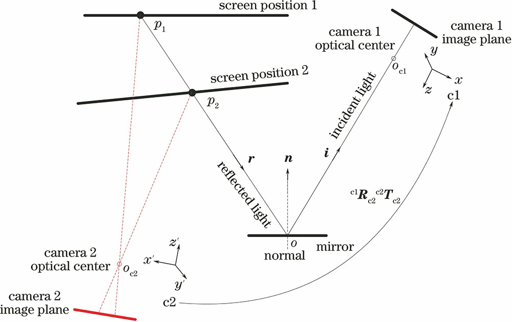
    Fig. 1. Schematic of deflectometry measurement method of single-camera monitoring
    Schematic of calibration. (a) Mirror calibration method; (b) rigid transformation of coordinate system
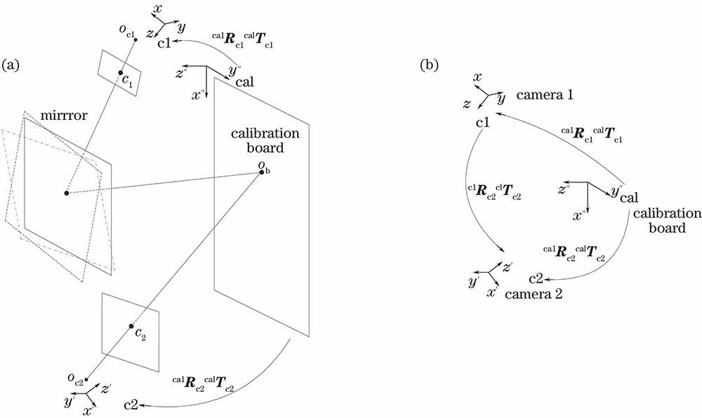
    Fig. 2. Schematic of calibration. (a) Mirror calibration method; (b) rigid transformation of coordinate system
    Deflectometry measurement system of single-monitoring
    Fig. 3. Deflectometry measurement system of single-monitoring
    Calibration of the positions of two cameras. (a), (b) and (c) are the fringe patterns from LCD captured by camera 1 through mirror reflection at three different positions; (d) is the fringe pattern from LCD captured by camera 2. The images in the red box represent the absolute phases
    Fig. 4. Calibration of the positions of two cameras. (a), (b) and (c) are the fringe patterns from LCD captured by camera 1 through mirror reflection at three different positions; (d) is the fringe pattern from LCD captured by camera 2. The images in the red box represent the absolute phases
    Simulation of the radial basis function. (a) Gradient in x direction; (b) gradient in y direction; (c) surface calculated from gradient data by the radial basis function interpolation; (d) simulated surface height error
    Fig. 5. Simulation of the radial basis function. (a) Gradient in x direction; (b) gradient in y direction; (c) surface calculated from gradient data by the radial basis function interpolation; (d) simulated surface height error
    (a) RMS error and (b) maximum error after introducing Gaussian noises in the simulation
    Fig. 6. (a) RMS error and (b) maximum error after introducing Gaussian noises in the simulation
    Absolute phases of phase shifting fringes of camera 1 and camera 2. (a) and (b) are the absolute phases of LCD at two positions captured by camera 1; (c) and (d) are the absolute phases of LCD at two positions captured by camera 2
    Fig. 7. Absolute phases of phase shifting fringes of camera 1 and camera 2. (a) and (b) are the absolute phases of LCD at two positions captured by camera 1; (c) and (d) are the absolute phases of LCD at two positions captured by camera 2
    Mirror surface calculation results. (a) Gradient in x direction; (b) gradient in y direction; (c) gradient error in x direction; (d) gradient error in y direction; (e) surface calculation from gradient data by the radial basis function interpolation; (f) surface height error
    Fig. 8. Mirror surface calculation results. (a) Gradient in x direction; (b) gradient in y direction; (c) gradient error in x direction; (d) gradient error in y direction; (e) surface calculation from gradient data by the radial basis function interpolation; (f) surface height error
    ParameterCamera 1Camera 2
    Focal length(2552.79,2551.53)(2568.33,2556.87)
    Principal point(655.18,508.69)(648.53,517.65)
    Distortion(-0.01663,-0.1786)(-0.1662,-0.7835)
    Pixel error(0.09,0.08)(0.10,0.08)
    Table 1. Calibration results of the intrinsic parameters of cameraspixel
    Chen Li, Xu Zhang, Dawei Tu, Junhui Jia, Wei Cui, Can Zhang. Deflectometry Measurement Method of Single-Camera Monitoring[J]. Acta Optica Sinica, 2017, 37(10): 1012007
    Download Citation