
Xing Peng, Lingbao Kong, "Design of a real-time fiber-optic infrared imaging system with wide-angle and large depth of field," Chin. Opt. Lett. 20, 011201 (2022)
- Chinese Optics Letters
- Vol. 20, Issue 1, 011201 (2022)
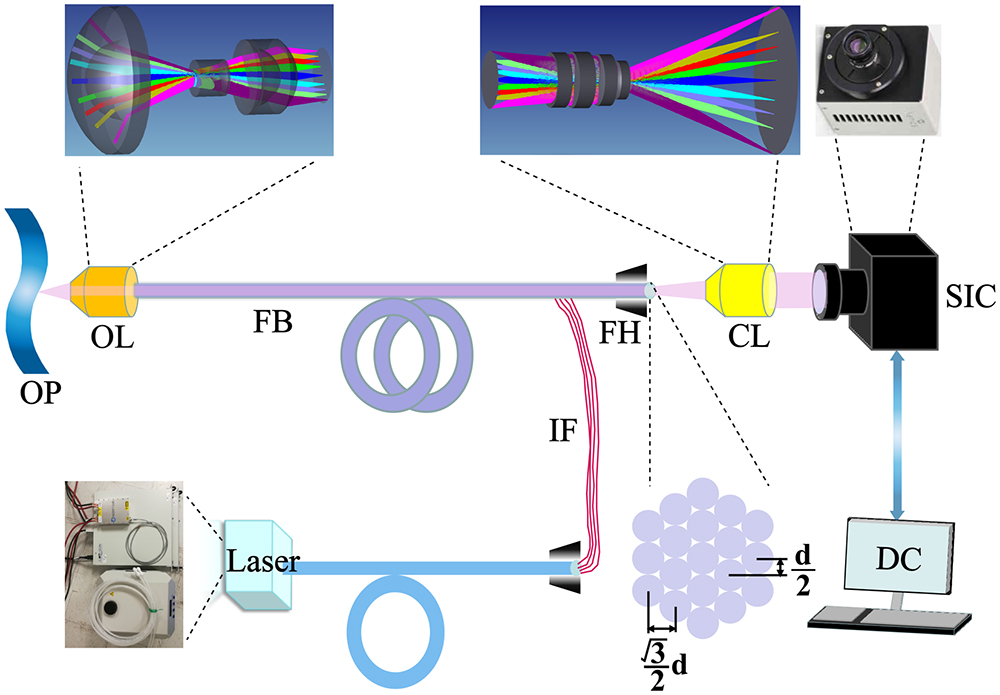
Fig. 1. Schematic diagram of the real-time fiber-optic infrared system (RFIS) with a large DOF. OP, objective plane; OL, objective lens; FB, fiber bundle; IF, illuminance fibers; CL, coupling lens; SIC, SWIR camera; DC, display and control.
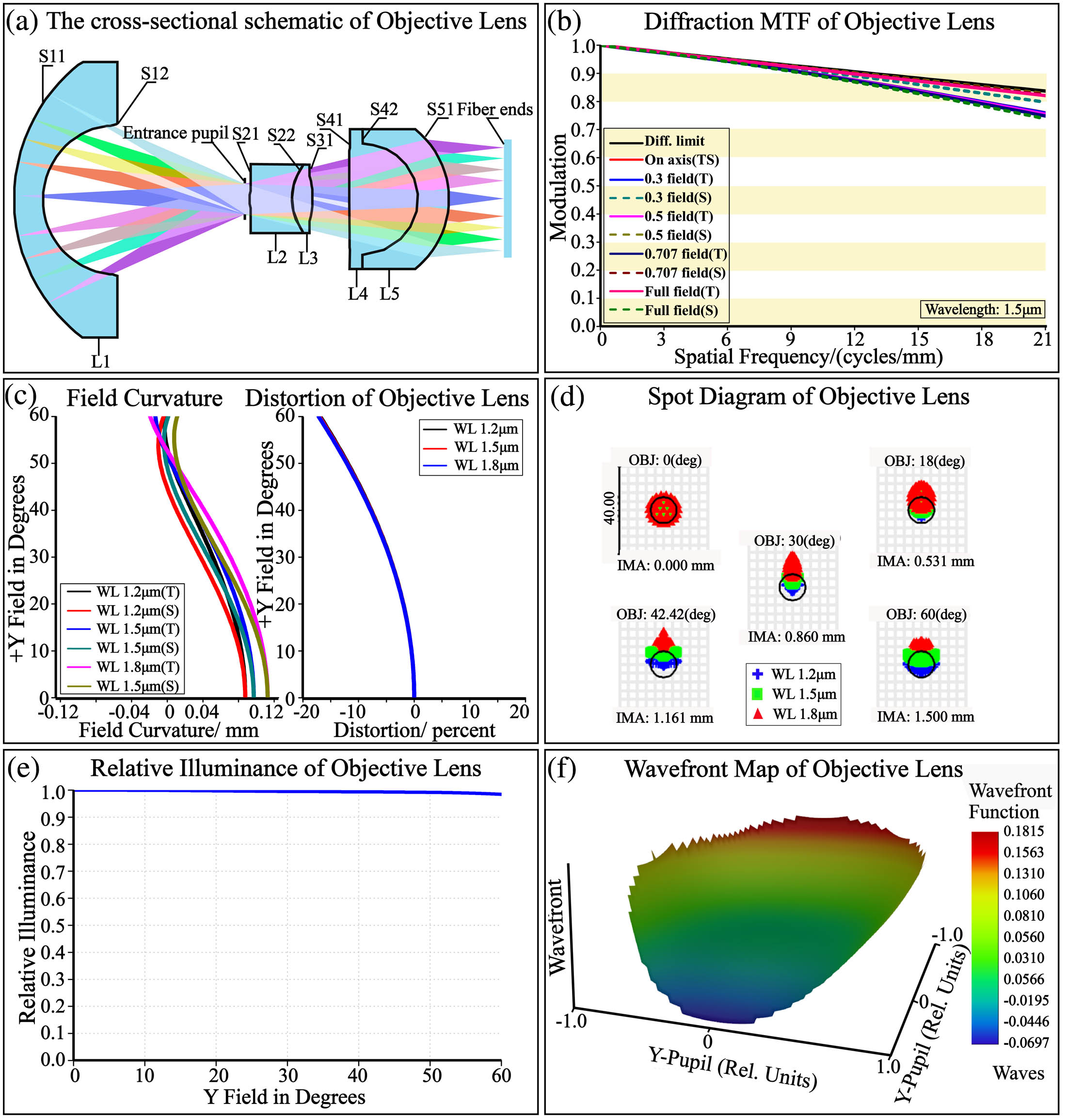
Fig. 2. Optical imaging quality evaluation of the RFIS. (a) Cross-sectional schematic of the OL in the RFIS. (b) Diffraction MTF values. (c) Field curvature and distortion plot. (d) Geometric spot diagrams. (e) Relative illuminance (RI) curve. (f) Wavefront map at FOV of 60°.
Fig. 3. Optical imaging quality evaluation of the RFIS. (a) Cross-sectional schematic of the CL in the RFIS. (b) Diffraction MTF values. (c) Field curvature and distortion plot. (d) Geometric spot diagrams. (e) RI curve. (f) Wavefront map at an FOV of 14.475°.
Fig. 4. MTF curves of the systems with different WDs for five radial image positions: on-axis, 0.3 field, 0.5 field, 0.707 field, and full field. (a) WD = 8 mm. (b) WD = 15 mm. (c) WD = 25 mm.
Fig. 5. Optical imaging results for evaluating the imaging quality of the RFIS. (a) The original image is a USAF 1951 resolution board. (b) The simulation image of the RFIS. (c) The undistorted image after computer processing with the distortion correction algorithm of image (b).
Fig. 6. Tolerance analysis and Monte Carlo analysis. (a) Tolerance analysis results of the OL. (b) The Monte Carlo analysis results of the OL. (c) Tolerance analysis results of the CL. (d) The Monte Carlo analysis results of the CL.
Fig. 7. Optical imaging results for evaluating the imaging quality of the RFIS. (a) The original image shows the corresponding gross anatomy of the tricuspid valve in a postmortem examination[21]. (c) The original image shows the tricuspid valve from an autopsy of the right ventricle[32]. (b) and (d) The undistorted images after computer processing with the distortion correction algorithm of images (a) and (c).
|
Table 1. Specification of the OL
|
Table 2. Specification of the CL
|
Table 3. Tolerance Value of the RFIS


Set citation alerts for the article
Please enter your email address

© Copyright 2018-2021 | Chinese Laser Press. All Rights Reserved 沪ICP备15018463号-20