
Xu Wang, Enlai Wang, Fang Wang, "Michelson interferometer composite cavity fiber laser sensor with radio frequency interrogation," Chin. Opt. Lett. 20, 040603 (2022)
- Chinese Optics Letters
- Vol. 20, Issue 4, 040603 (2022)
Abstract
Keywords
1. Introduction
Fiber optic interferometers based on the Michelson structure have been widely studied and applied to temperature[
In 1996, Kringlebotn et al. proposed using the laser beat technique to interrogate the wavelength variation of two orthogonal polarization modes in the laser[
In this paper, we propose a Michelson interferometer (MI) composite cavity fiber laser sensing system with radio-frequency (RF) detection. Unlike other composite cavity sensing systems[
Sign up for Chinese Optics Letters TOC. Get the latest issue of Chinese Optics Letters delivered right to you!Sign up now
2. Experimental Structure and Principle
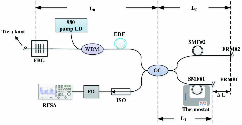
Figure 1 illustrates the schematic diagram of the compound laser system. The composite cavity fiber laser consists of a linear cavity, which is made of a piece of EDF pumped by a 980 nm pump source through a wavelength-division multiplexer (WDM) to provide stable enough gain for multiple mode lasing, and two reflectors. One of the reflectors is an FBG that can be used as a filter of the system. Another reflector is an MI, which includes an optical coupler (OC), two pieces of single mode fiber (SMF), and two Faraday rotating mirrors (FRMs) to form a composite cavity structure. Using the FRM as a reflector can control the polarization states of the two reflected beams so as to obtain a better interference effect. SMF#1 and SMF#2 are used as the sensing arm and the reference arm, respectively, and the length difference is
![]()
Figure 1.Schematic diagram of the system. FBG, fiber Bragg grating; WDM, wavelength division multiplexer; EDF, erbium-doped fiber; OC, optical coupler; SMF, single-mode fiber; FRM, Faraday rotating mirror; ISO, fiber optical isolator; PD, photo-detector; RFSA, radio-frequency spectrum analyzer.
The light entering the resonant cavity is split into two paths through the 50/50 OC. One beam propagating along SMF#1 is reflected by FRM#1; the other beam propagating along SMF#2 is reflected by FRM#2. Then, the two reflected lights interfere in the OC, and the output light spectrum after the interference is related to the optical path difference. The interference spectrum and the longitudinal mode of the fiber laser are superimposed on the PD to form a laser BFS with envelope modulation. The MI converts the variation of arm length difference into the change of interference wavelength. The BFS envelope varies with the interference wavelength changing.
The cavity mode of the laser cavity is shown in Fig. 2(a), and the longitudinal mode in the cavity is expressed as[
![]()
Figure 2.Schematic view of the laser modes: (a) the cavity modes of the laser cavity; (b) interference spectrum of the MI and overlap with the laser cavity modes; (c) modes of the composite cavity.
As shown in Fig. 2(b), the interference spectrum of the MI causes the envelope modulation of longitudinal mode frequency. By the selection of the interference spectrum of the MI, only those longitudinal modes that exceed the threshold value can generate laser output, and the selected longitudinal modes are shown in Fig. 2(c).
The BFS envelope generated by the composite cavity is obtained from the mutual beat between the longitudinal modes that exceed the threshold in Fig. 2(c), as shown in Fig. 3.
![]()
Figure 3.BFS envelope generated by the composite cavity.
The BFS envelope peak is expressed as
When the MI arm length difference
In Eq. (4),
3. Experimental Results and Analysis
The structure of this system is shown in Fig. 1. In the experiments, the FBG has the reflectivity of 90%, Bragg wavelength of 1549.83 nm, and 3 dB bandwidth of 0.077 nm. The end of the FBG is knotted to reduce the influence of external light on the system. The total cavity length of the laser resonator is 86 m, and the EDF is 6 m. The 980 nm pump source is launched into the resonant cavity through the WDM. In addition, an optical isolator is connected after the output port of the OC to ensure one-way transmission of the laser. The BFS, which is generated by the MLM, is detected by a photo-detector (PD) and observed by an RF spectrum analyzer.
As a comparison, the arm length difference
![]()
Figure 4.BFS envelope spectrum under different arm length differences: (a) the BFS envelope when the ΔL is 0.38 m; (b) the BFS envelope when the ΔL is 0.28 m.
The BFS envelope with the frequency of 1092 MHz in Fig. 4(a) and the BFS envelope with the frequency of 1106 MHz in Fig. 4(b) are chosen as the observation objects. When the spectral width is set to 60 MHz, the composition of the BFS envelope details corresponding to each is shown in Fig. 5.
![]()
Figure 5.Details of the selected observation BFS envelope: (a) the BFS envelope with center frequency of 1092 MHz; (b) the BFS envelope with center frequency of 1106 MHz.
As can be seen from Figs. 5(a) and 5(b), the longitudinal mode spacings of the BFS envelope details are both 1.2 MHz. The difference is that Fig. 5(b) has a higher number of longitudinal modes compared to Fig. 5(a). This is because the laser cavity length of the system is unchanged, and only the arm length difference of MI is changed, so the shorter the arm length difference, the larger the number of longitudinal modes. In addition, according to Eq. (1), the longitudinal mode spacing corresponding resonator cavity length L is 86.2 m, which is basically consistent with the set system cavity length of 86 m.
As a sensing arm, SMF#1 was fixed in a thermostat, and the sensing arm was the same for both sets of experiments, as shown in Fig. 1. Except for the part exposed to the outside of the instrument, about 69 m was heated in the experiment. The inner temperature of the thermostat can be detected by a thermo-couple with an accuracy of
The shifts of the selected BFS envelope with temperature are shown in Fig. 6. In particular, Fig. 6(a) displays the shift of the BFS envelope detail near 1092 MHz as the temperature increases with 25°C intervals. It can be seen that the BFS envelope increased from 1092.00 MHz to 1305.85 MHz as the temperature increased from 25°C to 150°C. Since there are a large number of longitudinal modes in the BFS envelope near 1106 MHz, which are not easy to observe, the BFS envelope with a spectral width of 300 MHz is selected for observation, as shown in Fig. 6(b). The figure records the shift of the BFS envelope as the temperature increases with 20°C intervals. It can be seen that the BFS envelope increased from 1106.00 MHz to 1310.25 MHz as the temperature increased from 30°C to 130°C.
![]()
Figure 6.Shift of BFS envelope with increasing temperature: (a) the shift of the BFS envelope with center frequency of 1092 MHz; (b) the shift of the BFS envelope with center frequency of 1106 MHz.
The responses of the measured BFS envelope to the temperature are shown in Fig. 7. In particular, Fig. 7(a) shows that the frequency varies linearly with temperature from 25°C to 150°C. The slope of the linear fitting is 1.68 MHz/°C at 1092 MHz, and the fitting degree is 99.491%. Figure 7(b) shows that the frequency varies linearly with temperature from 30°C to 130°C. The slope of the linear fitting is 2.04 MHz/°C at 1106 MHz, and the fitting degree is 99.369%.
![]()
Figure 7.Fitting result of frequency corresponding to the temperature change: (a) fitting result of the BFS envelope with center frequency of 1092 MHz; (b) fitting result of the BFS envelope with center frequency of 1106 MHz.
In the experiment of the fiber ring laser sensor for temperature measurement by Yin et al.[
In the experiment, the BFS envelope sensor signals are stable, although they may be disturbed by the environmental perturbations. Figure 8 shows a change in the BFS envelope of 1142 MHz over time. The BFS envelope is measured every 10 min for 50 min at 50°C. The center frequency of the BFS envelope is basically stable and hardly changes.
![]()
Figure 8.Stability of the BFS envelope under 50°C measured every 10 min for 50 min.
Figure 9(a) shows that the sensor fiber is tested for temperature drop, and the temperature is gradually decreased from 130°C to 30°C. The BFS envelope near 1106 MHz is recorded every 20°C. It can be seen that the BFS decreases from 1309.50 MHz to 1106.25 MHz as the temperature decreases 100°C. Figure 9(b) shows the comparison of fitting curves of temperature rises and drops, and their fitting degrees are 99.369% and 99.525%, respectively. Their sensitivities are 2.04 MHz/°C at 1106 MHz and 2.03 MHz/°C at 1106 MHz, respectively. The two fitting curves are basically identical, which further shows that the system has good stability and high sensitivity.
![]()
Figure 9.(a) Shift of BFS with center frequency of 1092 MHz; (b) comparison of the two fitting results.
4. Conclusions
In summary, an MI compound cavity fiber laser sensor with RF detection has been proposed and demonstrated. In the system, the BFS is generated by MLM in the laser cavity. Heating SMF#1 leads to a decrease in the arm length difference
References
[1] H. Sun, J. Zhang, Q. Rong, D. Feng, Y. Du, X. Zhang, D. Su, L. Zhou, Z. Feng, X. Qiao, M. Hu. A hybrid fiber interferometer for simultaneous refractive index and temperature measurements based on Fabry–Perot/Michelson interference. IEEE Sens. J., 13, 2039(2013).
[2] J. Yuan, K. Zhang, W. Yao, B. Liu, Q. Li, Z. Zhang, K. Zhang, R. Chen, S. Wang. A simple fiber lateral stress sensor based on polarization-maintaining fiber embedded Michelson interferometer assisted by silicon rubber sheets. Optik, 203, 164008(2019).
[3] D. Feng, M. Liu, W. Feng, B. Li. Michelson liquid-level sensor based on cascaded no-core fiber and single-mode fiber structure. Optik, 206, 163746(2019).
[4] F. Xie, J. Ren, Z. Chen, Q. Feng. Vibration-displacement measurements with a highly stabilised optical fiber Michelson interferometer system. Opt. Laser Technol., 42, 208(2010).
[5] O. Frazão, S. F. Silva, J. Viegas, J. M. Baptista, J. L. Santos, P. Royet. A hybrid Fabry–Perot/Michelson interferometer sensor using a dual asymmetric core microstructured fiber. Meas. Sci. Technol, 21, 025205(2010).
[6] M. Shao, H. Sun, J. Liang, L. Han, D. Feng. In-fiber Michelson interferometer in photonic crystal fiber for humidity measurement. IEEE Sens. J., 21, 1561(2021).
[7] H. Meng, W. Shen, G. Zhang, X. Wu, W. Wang, C. Tan, X. Huang. Michelson interferometer-based fiber-optic sensing of liquid refractive index. Sens. Actuators B Chem., 160, 720(2011).
[8] S. Zhang, Y. Liu, H. Guo, A. Zhou, L. Yuan. Highly sensitive vector curvature sensor based on two juxtaposed fiber Michelson interferometers with Vernier-like effect. IEEE Sens. J., 19, 2148(2019).
[9] X. Wang, T. Chen, D. Meng, F. Wang. A simple FBG Fabry–Perot sensor system with high sensitivity based on fiber laser beat frequency and Vernier effect. IEEE Sens. J., 21, 71(2021).
[10] J. T. Kringlebotn, W. H. Loh, R. I. Laming. Polarimetric Er3+-doped fiber distributed-feedback laser sensor for differential pressure and force measurements. Opt. Lett., 21, 1869(1996).
[11] H. K. Kim, S. K. Kim, H. G. Park, B. Y. Kim. Polarimetric fiber laser sensors. Opt. Lett., 18, 317(1993).
[12] B. Guan, L. Jin, Y. Zhang, H. Y. Tam. Polarimetric heterodyning fiber grating laser sensors. J. Light. Technol., 30, 1097(2012).
[13] S. Liu, Z. Yin, L. Zhang, L. Gao, X. Chen, J. Cheng. Multilongitudinal mode fiber laser for strain measurement. Opt. Lett., 35, 835(2010).
[14] W. Huang, S. Feng, W. Zhang, F. Li. DFB fiber laser static strain sensor based on beat frequency interrogation with a reference fiber laser locked to a FBG resonator. Opt. Express, 24, 12321(2016).
[15] S. Miao, W. Zhang, W. Huang, Y. Song. High-resolution static strain sensor based on random fiber laser and beat frequency interrogation. IEEE Photonics Technol. Lett., 31, 1530(2019).
[16] H. Luo, D. Liu, T. Liu, D. Lyu, Q. Sun. Beat frequency characterization and stabilization for short-cavity DBR fiber grating laser based sensor. IEEE Photonics J., 9, 2725309(2017).
[17] J. Tian, M. Hou, Y. Jiang, H. Luo, C. Tang. Fiber ring laser cavity for strain sensing via beat frequency demodulation. Opt. Commun., 476, 126326(2020).
[18] J. Zhang, G. D. Peng, L. Yuan, W. Sun. Composite-cavity-based Fabry–Perot interferometric strain sensors. Opt. Lett., 32, 1833(2007).
[19] J. Zhang, Q. Chai, Q. Hao, Y. Ge, X. Li, Q. Li, W. Sun, L. Yuan, G. Peng. Composite cavity fiber laser sensors based on weak feedback. Appl. Opt., 50, 5059(2011).
[20] Y. Gao, S. Liu, Y. Ni, H. Wu, X. Chen. Multi-longitudinal mode fiber laser sensor system with high signal-to-noise ratio based on laser modes control. Opt. Express, 27, 11776(2019).
[21] Z. Yin, L. Gao, S. Liu, L. Zhang, F. Wu, L. Chen, X. Chen. Fiber ring laser sensor for temperature measurement. J. Light. Technol., 28, 3403(2011).


Set citation alerts for the article
Please enter your email address

© Copyright 2018-2021 | Chinese Laser Press. All Rights Reserved 沪ICP备15018463号-20