
Konrad Tschernig, Roberto de J. León-Montiel, Armando Pérez-Leija, Kurt Busch. Multiphoton synthetic lattices in multiport waveguide arrays: synthetic atoms and Fock graphs[J]. Photonics Research, 2020, 8(7): 1161
- Photonics Research
- Vol. 8, Issue 7, 1161 (2020)
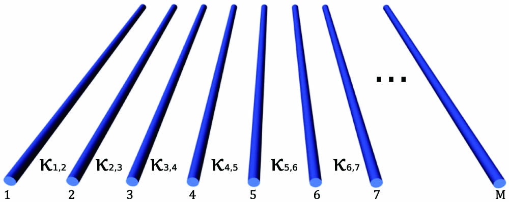
Fig. 1. 1D array of M κ m , m + 1
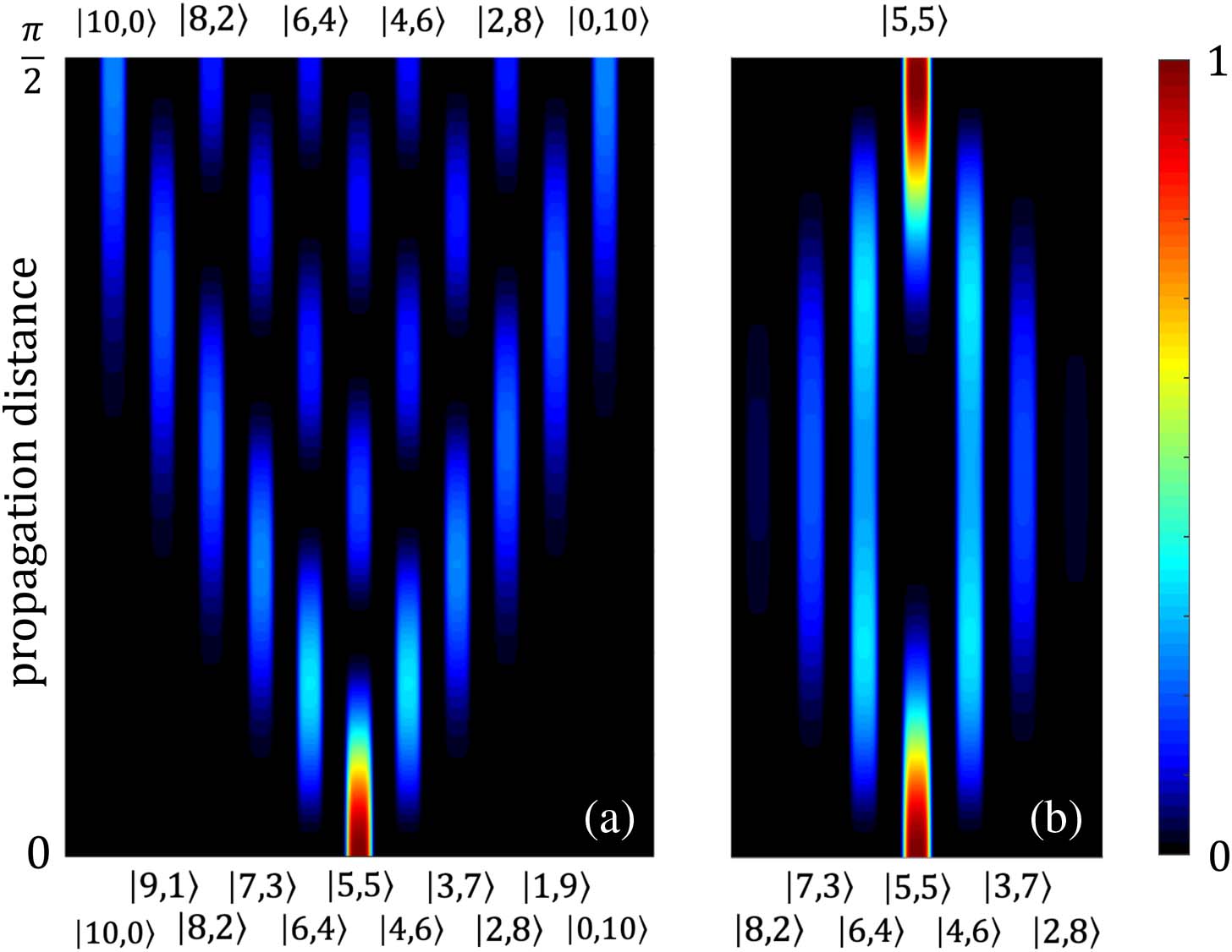
Fig. 2. Probability distribution | ⟨ m , N − m | U ^ ( z ) | ψ ( 0 ) ⟩ | 2 | ψ ( 0 ) ⟩ = | 5 , 5 ⟩ β 1 = β 2 = 1 β 1 = 0 β 2 = 4
Fig. 3. Probability distribution | ⟨ n 1 , n 2 , n 3 | U ^ ( z ) | ψ ( 0 ) ⟩ | 2 | ψ ( 0 ) ⟩ = | 1 , 0 , 1 ⟩ κ 1 = κ 2 = 1 β 1 = β 2 = β 3 = 0 β 1 = β 3 = 0 β 2 = 2
Fig. 4. Pseudo-energy term diagrams for (a) N = 1 M = 3 N = 2 M = 2 N = 2 M = 3
Fig. 5. Matrix components of the effective Hamiltonian H μ ν N = 2 M = 3 β 1 = β 2 κ 1 = κ 2 = 1
Fig. 6. (a) 2D Fock graph for M = 3 N = 2 5 according to Eq. (31 ). (b) Sample trial implementation of the ( M = 3 , N = 2 )
Fig. 7. (a) Overview of several 2D and 3D embeddings of Fock graphs A μ , ν ( N , M ) M = 2 , … , 6 N = 1 , … , 5 N ≥ 3 , M ≥ 4 M ≥ 5 , N ≥ 4 N = 2 , M = 4 N = 3 , M = 3
Fig. 8. Evolution of the probabilities | ⟨ K ν | U ^ ( z ) | ψ ⟩ | 2 | ψ ⟩ 37 ).
Table 1. Possible Lattice Configurations for States Arising in a Waveguide Trimer Excited by Two Photons

Set citation alerts for the article
Please enter your email address
© Copyright 2018-2021 | Chinese Laser Press. All Rights Reserved 沪ICP备15018463号-20