• Photonics Research
  • Vol. 9, Issue 5, 803 (2021)
Junli Qi1、2、3、4, Weihua Wang1、2、5、6、*, Bo Shi4, Hui Zhang4, Yanan Shen4, Haifei Deng4, Wenjing Pu4, Xin Liu4, Huihui Shan4, Xiaomin Ma4, Lianqiang Zhang4, Wei Lu5, Meicheng Fu3, and Xiujian Li3、7、*
Author Affiliations
  • 1Institute of Plasma Physics, Hefei Institutes of Physical Sciences, Chinese Academy of Sciences, Hefei 230031, China
  • 2Science Island Branch of Graduate School, University of Science and Technology of China, Hefei 230031, China
  • 3College of Liberal Arts and Sciences, National University of Defense Technology, Changsha 410073, China
  • 4Institute of Applied Physics, Army Academy of Artillery and Air Defense, Hefei 230031, China
  • 5Institute of Physical Science and Information Technology, Anhui University, Hefei 230031, China
  • 6e-mail: whwang@ipp.ac.cn
  • 7e-mail: xjli@nudt.edu.cn
  • show less
    DOI: 10.1364/PRJ.419561 Cite this Article Set citation alerts
    Junli Qi, Weihua Wang, Bo Shi, Hui Zhang, Yanan Shen, Haifei Deng, Wenjing Pu, Xin Liu, Huihui Shan, Xiaomin Ma, Lianqiang Zhang, Wei Lu, Meicheng Fu, Xiujian Li. Concise and efficient direct-view generation of arbitrary cylindrical vector beams by a vortex half-wave plate[J]. Photonics Research, 2021, 9(5): 803 Copy Citation Text show less
    Fast axis distributions of several VHPs with σ=0. (a)–(d) are the distributions with m=1, 2, 3, 4, respectively.
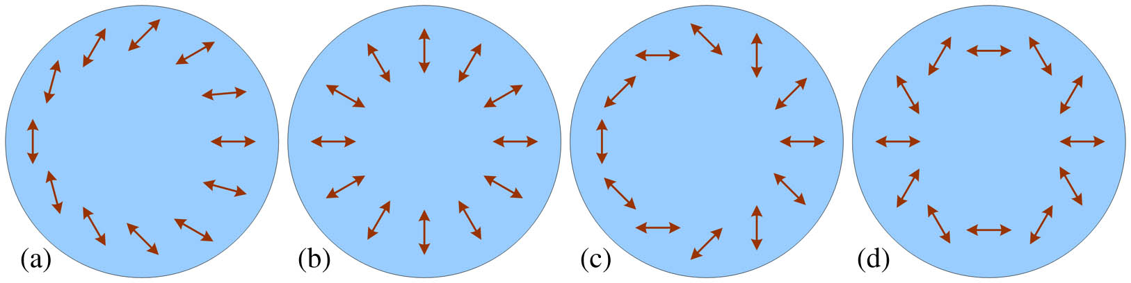
    Fig. 1. Fast axis distributions of several VHPs with σ=0. (a)–(d) are the distributions with m=1, 2, 3, 4, respectively.
    Polarization distributions of various one-order CVP beams. (a)–(f) correspond to the polarization distributions of ERP,EAP,Eπ/41,E−π/41,EARP,EAAP.
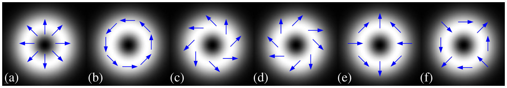
    Fig. 2. Polarization distributions of various one-order CVP beams. (a)–(f) correspond to the polarization distributions of ERP,EAP,Eπ/41,Eπ/41,EARP,EAAP.
    Direct-view experimental setup for the generation and double-slit interference of CV beams. Lenses 1 and 2 constitute a beam expander; HP, half-wave plate; GTP, Gran Taylor prism; QP, quarter-wave plate; VHP, vortex half-wave plate.
    Fig. 3. Direct-view experimental setup for the generation and double-slit interference of CV beams. Lenses 1 and 2 constitute a beam expander; HP, half-wave plate; GTP, Gran Taylor prism; QP, quarter-wave plate; VHP, vortex half-wave plate.
    Intensity distributions of generated first-order CV beams. (a)–(f) ERP,EAP,Eπ/41,E−π/41,EARP,EAAP. Arrow heads represent the transmission direction of the polarizers.
    Fig. 4. Intensity distributions of generated first-order CV beams. (a)–(f) ERP,EAP,Eπ/41,Eπ/41,EARP,EAAP. Arrow heads represent the transmission direction of the polarizers.
    Polarization azimuth distributions of generated first-order CV beams. (a)–(f) ERP,EAP,Eπ/41,E−π/41,EARP,EAAP. Arrow heads represent the polarization direction.
    Fig. 5. Polarization azimuth distributions of generated first-order CV beams. (a)–(f) ERP,EAP,Eπ/41,Eπ/41,EARP,EAAP. Arrow heads represent the polarization direction.
    Stokes parameters and polarization parameters of generated second-order and third-order CV beams. (a), (b) Second-order and third-order RP beams; (c), (d) second-order and third-order AP beams. 1–6: S1, S2, S3, DOP, PA, PE.
    Fig. 6. Stokes parameters and polarization parameters of generated second-order and third-order CV beams. (a), (b) Second-order and third-order RP beams; (c), (d) second-order and third-order AP beams. 1–6: S1, S2, S3, DOP, PA, PE.
    Intensity and polarization distributions of generated first-order and third-order ARCV and CLCV beams. (a), (b) First-order and third-order ARCV beams; (c), (d) first-order and third-order CLCV beams; I0, intensity; ψ, PA; χ, PE.
    Fig. 7. Intensity and polarization distributions of generated first-order and third-order ARCV and CLCV beams. (a), (b) First-order and third-order ARCV beams; (c), (d) first-order and third-order CLCV beams; I0, intensity; ψ, PA; χ, PE.
    Experimental results of double-slit interference of first-order to third-order ARCV and CLCV beams. (a)–(c) First-order to third-order ARCV beams; (d)–(f) first-order to third-order CLCV beams; p1−p3, horizontal pixel positions with equal transverse fringes at y=50; p4−p6, corresponding horizontal pixel positions with equal transverse fringes at y=450.
    Fig. 8. Experimental results of double-slit interference of first-order to third-order ARCV and CLCV beams. (a)–(c) First-order to third-order ARCV beams; (d)–(f) first-order to third-order CLCV beams; p1p3, horizontal pixel positions with equal transverse fringes at y=50; p4p6, corresponding horizontal pixel positions with equal transverse fringes at y=450.
    Experimental results of double-slit interference of first-order to third-order CV beams. (a)–(c) First-order RP beam; second-order π/4 beam; third-order AP beam.
    Fig. 9. Experimental results of double-slit interference of first-order to third-order CV beams. (a)–(c) First-order RP beam; second-order π/4 beam; third-order AP beam.
    Experimental results of generated A-CVV beams. (a)–(d) Intensities of A-R1V3, A-R3V1, A-A1V3, and A-A3V1 beams; 1, intensity after a 0° polarizer; 2, intensity after a 45° polarizer; 3, PA; 4, PE. Arrow heads indicate the transmission direction of the polarizers.
    Fig. 10. Experimental results of generated A-CVV beams. (a)–(d) Intensities of A-R1V3, A-R3V1, A-A1V3, and A-A3V1 beams; 1, intensity after a 0° polarizer; 2, intensity after a 45° polarizer; 3, PA; 4, PE. Arrow heads indicate the transmission direction of the polarizers.
    Stokes parameters and polarization parameters of generated C-CVV beams. (a)–(d) C-R1V3, C-R3V1, C-A1V3, and C-A3V1 beams; 0–5: S0, S1, S2, S3, PA, PE.
    Fig. 11. Stokes parameters and polarization parameters of generated C-CVV beams. (a)–(d) C-R1V3, C-R3V1, C-A1V3, and C-A3V1 beams; 0–5: S0, S1, S2, S3, PA, PE.
    Experimental results of double-slit interference of anti-clockwise and clockwise CVV beams. (a)–(d) A-R1V3 beam, A-A3V1 beam, C-A1V3 beam, and C-R3V1 beam.
    Fig. 12. Experimental results of double-slit interference of anti-clockwise and clockwise CVV beams. (a)–(d) A-R1V3 beam, A-A3V1 beam, C-A1V3 beam, and C-R3V1 beam.
    Figurep1p2p3p4p5p6Nd0dR=d/d0l
    8(a)2173184182333344341020.1160.79601
    8(b)2113124112433454441020.0532.66671.62932.0467
    8(c)217297376265345425819.937548.33332.42423.0454
    8(d)2403404402243254241020−15.6667−0.7833−1
    8(e)2463464452133144131019.95−32.3333−1.6207−2.069
    8(f)275354433227306386819.8125−47.6667−2.4059−3.0713
    Table 1. Measured Values of Pixel Positions and Topological Charge Number
    Junli Qi, Weihua Wang, Bo Shi, Hui Zhang, Yanan Shen, Haifei Deng, Wenjing Pu, Xin Liu, Huihui Shan, Xiaomin Ma, Lianqiang Zhang, Wei Lu, Meicheng Fu, Xiujian Li. Concise and efficient direct-view generation of arbitrary cylindrical vector beams by a vortex half-wave plate[J]. Photonics Research, 2021, 9(5): 803
    Download Citation