
Junli Qi, Weihua Wang, Bo Shi, Hui Zhang, Yanan Shen, Haifei Deng, Wenjing Pu, Xin Liu, Huihui Shan, Xiaomin Ma, Lianqiang Zhang, Wei Lu, Meicheng Fu, Xiujian Li. Concise and efficient direct-view generation of arbitrary cylindrical vector beams by a vortex half-wave plate[J]. Photonics Research, 2021, 9(5): 803
- Photonics Research
- Vol. 9, Issue 5, 803 (2021)
Abstract
1. INTRODUCTION
With a cylindrically symmetric intensity profile and a variable polarization endowed with a vortex phase about the beam axis, cylindrical vector (CV) beams have attracted widespread attention [1,2]. As a typical representative of CV beams, the radially polarized (RP) and azimuthally polarized (AP) beams have been found to have important applications in the fields such as tight focusing [3–5], beam shaping [6–9], particle accelerating and trapping [10–14], laser materials processing [15–17], superresolution techniques [18–20], and optical metrology [21–23]. Recent studies have also demonstrated potential applications of CV beams in optical communication [24–26], quantum information processing [27–29], spin and orbital angular momentum effects [30–34], inverse energy flux [35,36], plasmonic nanostructures [37,38], and fiber and integrated optics [39–42].
Various techniques and schemes have been developed to generate CV beams. Generally, these methods can be categorized into two classes: intracavity (active) and external conversion (passive) [1]. The intracavity method is to generate CV beams directly in the laser by putting in special optical elements; the internal structure of the laser needs to be adjusted accordingly, including the use of crystal birefringence [43–45], Brewster angle characteristics [46,47], cavity configuration design [48], and geometric phase control [49]. These methods can generate vector beams with high quality and energy conversion efficiency but lack flexibility due to limited space and complex technology to reconstruct the existing laser. The external conversion method refers to transforming spatially uniform polarized beams into CV beams through certain phase devices or decomposition and recombination outside the laser. The commonly used external devices include segmented spiral varying retarders [50–52], special phase plates [53,54], anisotropic crystals [55–58], diffractive optical elements [59,60], subwavelength gratings [61–63], and metasurfaces [64–67]. However, these conversion methods have the problems of low conversion efficiency and high design cost. Interferometric devices have also been proposed to generate CV beams, such as Sagnac interferometers [68–71], Mach–Zehnder interferometers [72,73], and other interferometers [74–78]. But the interferometric methods often need high stability and precise control, which reduces conversion efficiency and accuracy. Nowadays, the spatial light modulator (SLM) is mostly used to realize CV beams, including the double SLM method [79–82] and split-screen method by a single SLM [83–88]. However, the double SLM method is not cost-effective, and the split-screen method has the drawback of low SLM area utility. In addition, due to the diffraction effect, the SLM method has low conversion efficiency and cannot withstand high-energy laser beams because of the liquid crystal material.
Herein, we demonstrate a concise, efficient, and practical direct-view method to generate arbitrary CV beams by vortex half-wave plate (VHP) without beam reflection and deflection, including realizing CV beams, vortex beams, and CVV beams. The VHP is a special half-wave plate (HP) with a consistent delay , but the direction of the fast axis changes continuously around the circle center. It has high transmittance just like an HP, so it has high energy utilization and can be made up to 2 inches, which can realize the conversion of high-energy beams through beam expansion and recompression. In addition, new types of VHPs can be formed by cascading two or more VHPs when the types of available VHPs are limited, which helps in more flexible generation of multitype CV beams.
Sign up for Photonics Research TOC. Get the latest issue of Photonics Research delivered right to you!Sign up now
In this paper, six kinds of first-order and other high-order CV beams, such as the RP beam, AP beam, and three-order AP beam, are formed by simply rotating an HP. The Stokes parameters and double-slit interference of multitype CV beams are investigated in detail. The polarization parameters, including degree of polarization (DOP), polarization azimuth, and ellipticity, are obtained, which demonstrates the efficient generation of the CV beams. Additionally, misplacement and tilt appear in the double-slit interference fringes of CVV beams, in which the misplacement number is for and for , where is the polarization order number, and the fringe tilt offset is positively related to the topological charge number of the CVV beams. It is experimentally demonstrated that arbitrary CV beams with high quality are effectively achieved by the proposed setup, and the double-slit interference method can be utilized to determine and analyze CV beams rapidly and concisely through practical performance.
2. PRINCIPLES
A. VHP
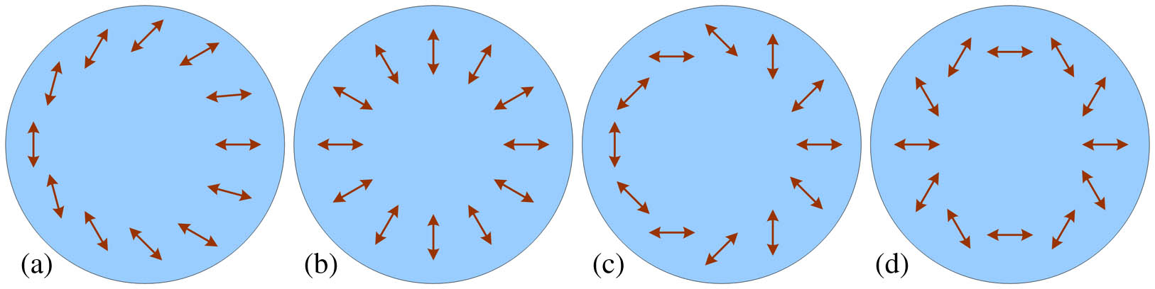
Figure 1.Fast axis distributions of several VHPs with
The VHP Jones matrix with fast axis at the direction can be expressed as
When is a negative value, it represents an anti-clockwise rotation, and a positive value denotes a clockwise rotation. Taking the first-order and fourth-order VHPs as examples, the VHP(1, 0) can be converted to VHP(1, ) by rotating 30° anti-clockwise. Similarly, the VHP(4, 0) becomes VHP(4, ) by rotating 30° clockwise. And the VHP(4, ) (or ) will be obtained by rotating the VHP(4, 0) by 30° anti-clockwise.
B. Generation of CV Vector Beams
We will take the VHP with to generate arbitrary first-order CV beams, for example. When the incident beam is horizontally polarized with the Jones vector , for the VHP(1, 0), the Jones vector of the transmitted beam is expressed as
It means that each polarization direction is rotated 45° anti-clockwise on the basis of radial polarization, which is called the first-order -CV beam. The superscript 1 in represents polarization order number of CV beams. Also, can be obtained by inputting a horizontally polarized beam for the VHP(1, ) or VHP(1, ) as the following:
We can get multitype CV beams by directly rotating the VHP with when the horizontally or vertically polarized beam is input. But this method cannot obtain other second-order CV beams except for the second-order RP beam, and with the increase of order , the rotation angle of VHP becomes smaller, and the accuracy will be more difficult to control. Taking the high-order AP beam (requiring ) as an example, according to Eq. (3), the rotation angle of VHP with is . Obviously, the larger the order (for ) is, the smaller the rotation angle of VHP with becomes, and the higher rotation accuracy is needed.
So, the method of changing the polarization direction of an incident linearly polarized beam by rotating an HP to generate CV beams is proposed without rotating the VHP. And the polarization direction of the incident beam need not change with the increase of the order for generating the same kind of other high-order CV beams. When the incident beam is a linearly polarized one, with the polarization direction orientated at according to the horizontal direction ( axis) for the VHP(, 0), the Jones vector of the transmitted beam is expressed as the following:
This means that each polarization direction is rotated by anti-clockwise on the basis of the radial polarization. The superscript m in represents polarization order number of the CV beams. So, the can be obtained when , , , and , respectively.
In addition, when the RP beam passes through an HP with the fast axis in the horizontal (or vertical) direction, i.e., 0° HP (or 90° HP) with the Jones matrix described as (or ), the Jones vector of the transmitted beam is expressed as
That is, the polarization direction at the azimuth angle is , which is called anti-vortex radial polarization (ARP) [89] or quasi-radial polarization (q-RP) [90] mode with the polarization order number . When the AP beam passes through the 0° HP, or the RP beam passes through an HP with the fast axis at 45° direction with the Jones matrix , the Jones vector of the transmitted beam is expressed as
The polarization direction is at the azimuth angle , which is called the anti-vortex azimuthal polarization (AAP) or quasi-azimuth polarization (q-AP) mode. For instance, in the direction of azimuth angle , the polarization direction is 90°, at , the polarization direction is 45°, and at , the polarization direction is . In the same azimuth direction, the polarization direction of the AAP mode is that of the ARP mode rotated 90° anti-clockwise.
![]()
Figure 2.Polarization distributions of various one-order CVP beams. (a)–(f) correspond to the polarization distributions of
The high-order CV beams will be obtained when a linearly polarized beam passes through the VHP with .
C. Generation of Vortex Beams
The Jones matrix of a quarter-wave plate (QP) with fast axis in direction relative to the horizontal direction ( axis) is expressed as follows:
When the horizontally polarized beam passes through the QPs with fast axis in 45° and direction, respectively, right-handed and left-handed circularly polarized beams will be obtained with the corresponding Jones vectors described as and .
The VHP(, ) can transform an incident circularly polarized beam into a vortex wavefront. When the incident beam is left-handed circularly polarized, the transmitted beam is a vortex one with the topological charge number , and the polarization state becomes right-handed circularly polarized. The corresponding Jones vector is as follows:
When the incident beam is a right-handed circularly polarized beam, the exit beam is a vortex beam with topological charge number , and the polarization state becomes left-handed circularly polarized. The corresponding Jones vector is as follows:
D. Generation of CVV Beams
When the circularly polarized vortex beam passes through a QP with the fast axis in 45° or direction, it can be converted into a linearly-polarized vortex (LV) beam. The conversion process of the Jones vector is as follows:
An anti-clockwise vertically linearly polarized vortex (AVLV) beam is obtained when the ARCV beam passes through the QP with the fast axis at 45°, and an anti-clockwise horizontally linearly polarized vortex (AHLV) beam is obtained when the ARCV beam passes through the QP with the fast axis at .
Similarly, when the CLCV beam passes through the QP with the fast axis at 45°, a clockwise horizontally linearly polarized vortex (CHLV) beam is obtained. And a clockwise vertically linearly polarized vortex (CVLV) beam is obtained when the CLCV beam passes through the QP with the fast axis at . The conversion process of Jones vector is as follows:
Combined with Section 2.B, it is easy to find that a CVV beam can be obtained when a generated LV beam passes through another VHP. The corresponding Jones vector is depicted as follows:
The -order radially polarized vortex (RPV) beam with topological charge number is generated when the AHLV beam with passes through the second -order VHP with . Similarly, an -order azimuthally polarized vortex (APV) beam with is generated when the CVLV beam with passes through the second -order VHP with . The conversion process of Jones vector is as follows:
E. Increasing Types of VHP
New types of VHPs can be formed by cascading two or more VHPs when the types of available VHPs are limited. The cascading of two and three VHPs is described, respectively, in detail. The combined Jones matrix of two VHPs can be expressed as
Taking the combination of the first-order and third-order VHPs with , for example, when passing through the 0° HP, first-order and third-order VHPs successively, the combination result is equivalent to the VHP(2, 0). And when passing through the 0° HP, third-order and first-order VHPs in turn, the cascaded one corresponds to the VHP(, 0). The negative sign indicates that the fast axis of the VHP changes continuously clockwise. In particular, when 0° HP is placed between the two VHPs, the VHP(4, 0) is formed. The combined Jones matrix of three VHPs can be expressed as
It can be found from the expression that the cascaded device forms the new VHP with . Taking the VHPs with , 3, and 7, for example, the VHPs with , , , , , 6, , 8, 9, and 10 can be generated by cascading two or three of the VHPs, in which 0° HP can be placed when necessary. Similarly, the combination of five VHPs can form the new VHP with . By analogy, more types of VHPs can be generated.
3. EXPERIMENTAL SETUP
![]()
Figure 3.Direct-view experimental setup for the generation and double-slit interference of CV beams. Lenses 1 and 2 constitute a beam expander; HP, half-wave plate; GTP, Gran Taylor prism; QP, quarter-wave plate; VHP, vortex half-wave plate.
The components in the dashed lines can be arranged or not according to the beams needed, and the HPs and QPs can be rotated accordingly. Multiple types of first-order or higher-order CV beams, such as the RP, AP, and -CV beams, can be generated by rotating the HP2 when there are no components in the dashed lines. When only the HP3 in the red dashed line is added to the experimental setup, the ARP and AAP beams can be generated by rotating the HP3. When only the QP1 in the green dashed line is added to the experimental setup, the linearly polarized beam is converted into a circularly polarized beam, and after passing through the VHP1, a vortex beam with circular polarization is obtained. Meanwhile, if QP2 and VHP2 in the blue dashed line are added to the experimental setup, the CVV beam can be generated.
The intensity distribution of the generated beam is captured by the CCD camera, which is a Manta G-033B modal 8-bit product of AVT Company with the resolution of and a pixel pitch of . A double slit with the slit width of 99 μm and slit spacing of 1 mm in the black dashed line can be placed in front of the camera to help detect the generated CV beams.
In the experimental setup, the VHP is supplied by LBTEK (Changsha Lubang Photonics Technology Co., Ltd.), which is a liquid crystal polymer wave plate with a fast axis rotating continuously along an azimuthal coordinate, whose function resembles the general q-plate [91–94] and S-wave plate [95–97]. The general q-plate is essentially a thin (nematic) liquid crystal film sandwiched between two coated plane glasses, which needs extra electric or temperature control. And the S-wave plate, a kind of metasurface, is a nanosubwavelength periodic structure applied in the visible region, usually written inside a glass plate by femtosecond laser, behaving as a uniaxial crystal with the optical axes parallel and perpendicular to the subwavelength grooves. These devices are characterized by singular optic axis distributions with topological charge and are commonly called by the joint name q-plates [98,99].
4. RESULTS AND DISCUSSION
![]()
Figure 4.Intensity distributions of generated first-order CV beams. (a)–(f)
In order to get the spatial polarization distributions of generated beams, Stokes parameters , , , and are measured by the combination of a polarizer and a QP in the following equation:
Polarization parameters, including DOP, polarization azimuth (PA), and polarization ellipticity (PE), can be obtained by the following:
![]()
Figure 5.Polarization azimuth distributions of generated first-order CV beams. (a)–(f)
![]()
Figure 6.Stokes parameters and polarization parameters of generated second-order and third-order CV beams. (a), (b) Second-order and third-order RP beams; (c), (d) second-order and third-order AP beams. 1–6:
![]()
Figure 7.Intensity and polarization distributions of generated first-order and third-order ARCV and CLCV beams. (a), (b) First-order and third-order ARCV beams; (c), (d) first-order and third-order CLCV beams;
![]()
Figure 8.Experimental results of double-slit interference of first-order to third-order ARCV and CLCV beams. (a)–(c) First-order to third-order ARCV beams; (d)–(f) first-order to third-order CLCV beams;
The specific tilt offsets are measured by pixel positions with equal transverse fringes. There are 10 fringes between and because of relatively little offset for shown in Figs. 8(a), 8(b), 8(d), and 8(e), and 8 fringes for shown in Figs. 8(c) and 8(f). To ensure the relative accuracy of measurement, to are selected at the same ordinate . And to , selected at the same ordinate , are on the same stripe as to , respectively. The measured values are shown in Table 1. The fringe spacing is obtained by , in which is the fringe number between (or ) and (or ). The fringe offset is obtained by , and the relative offset coefficient is defined as the ratio of to , i.e., . Measured Values of Pixel Positions and Topological Charge NumberFigure 217 318 418 233 334 434 10 20.1 16 0.7960 1 211 312 411 243 345 444 10 20.05 32.6667 1.6293 2.0467 217 297 376 265 345 425 8 19.9375 48.3333 2.4242 3.0454 240 340 440 224 325 424 10 20 −15.6667 −0.7833 −1 246 346 445 213 314 413 10 19.95 −32.3333 −1.6207 −2.069 275 354 433 227 306 386 8 19.8125 −47.6667 −2.4059 −3.0713
Theoretically, the relative offset coefficient should be an integer equal to the topological charge if the double-slit spacing is close to 0 and the beam size approaches infinity. However, due to the existence of double slit spacing and limited beam size, the two-slit phase difference of the top part of the double slit is not 0, and the one of the bottom part of the double slit is less than , in which is the topological charge number, so the phase difference of the top and bottom parts of the double slit is less than , i.e., the offset of interference fringes is less than fringes. But, the ratio of of vortex beam with to (or for ) is close to the topological charge , which could be expressed as follows:
The topological charge can be calculated based on Eq. (24). The corresponding measurement results are listed in Table 1. It is found that the measured results are in good agreement with the theoretical values except for a little deviation, which can be improved by increasing the camera pixels and reducing the pixel size.
![]()
Figure 9.Experimental results of double-slit interference of first-order to third-order CV beams. (a)–(c) First-order RP beam; second-order
In theory, the misplacement region number should be equal to in the condition that the double-slit spacing is rather small (approximately 0). However, with the increase of the polarization number , the polarization information of the HCV beam at the top and bottom of the double slit is masked because of non-zero double-slit spacing, and then misplacement regions reduce two parts. In this experiment, the missing appeared in the HCV beam with . If the double-slit spacing becomes larger, the missing may happen in the second-order CV beam. Similarly, if the spacing becomes smaller, the missing will be delayed to a higher-order CV beam. As shown in Fig. 9, although the fringe distributions of second-order and third-order CV beams both have five layers, their distribution density in the middle region is different. The higher the polarization order is, the denser the layers are.
![]()
Figure 10.Experimental results of generated A-CVV beams. (a)–(d) Intensities of A-R1V3, A-R3V1, A-A1V3, and A-A3V1 beams; 1, intensity after a 0° polarizer; 2, intensity after a 45° polarizer; 3, PA; 4, PE. Arrow heads indicate the transmission direction of the polarizers.
![]()
Figure 11.Stokes parameters and polarization parameters of generated C-CVV beams. (a)–(d) C-R1V3, C-R3V1, C-A1V3, and C-A3V1 beams; 0–5:
![]()
Figure 12.Experimental results of double-slit interference of anti-clockwise and clockwise CVV beams. (a)–(d) A-R1V3 beam, A-A3V1 beam, C-A1V3 beam, and C-R3V1 beam.
The topological charge number is calculated by measuring the tilt offset. The specific measurement process is the same as that of vortex beam. As shown in Fig. 12, the tilt offset between two red vertical lines of A-R1V3 beam is three times of that of A-A3V1 beam, and C-A1V3 beam has three times the offset of C-R3V1, i.e., for A-R1V3, and for C-R3V1 beam.
5. CONCLUSION
In summary, we have demonstrated a concise efficient and practical direct-view method to generate arbitrary CV beams by VHP, including realizing CV beams, vortex beams and CVV beams. The characteristics of VHP are analyzed in detail. New types of VHPs can be formed by cascading two or more VHPs when the types of available VHPs are limited, which helps to generate multi-type CV beams more flexibly. Six kinds of first-order and other high-order CV beams, such as the RP beam, AP beam, and third-order AP beam, are formed by simply rotating an HP. The Stokes parameters and double-slit interference of multi-type CV beams are investigated in detail. The polarization parameters, including DOP, polarization azimuth, and ellipticity, are obtained, which demonstrates the efficient generation of CV beams.
In addition, misplacement and tilt appear in the double-slit interference fringes of the CVV beams, in which the misplacement number is for and for , where is the polarization order number, and the fringe tilt offset is positively related to the topological charge number of CVV beams. It is experimentally demonstrated that arbitrary CV beams with high quality are effectively achieved by the proposed setup, and the double-slit interference method can be utilized to determine and analyze CV beams rapidly and concisely by practical performance, which shows its potential to be implemented as a commercial device.
Acknowledgment
Acknowledgment. The authors acknowledge assistance from Dr. Jie Xu and Dr. Ziyang Yuan.
References
[1] Q. Zhan. Cylindrical vector beams: from mathematical concepts to applications. Adv. Opt. Photon., 1, 1-57(2009).
[2] U. Levy, Y. Silberberg, N. Davidson. Mathematics of vectorial Gaussian beams. Adv. Opt. Photon., 11, 828-891(2019).
[3] K. S. Youngworth, T. G. Brown. Focusing of high numerical aperture cylindrical-vector beams. Opt. Express, 7, 77-87(2000).
[4] R. Dorn, S. Quabis, G. Leuchs. Sharper focus for a radially polarized light beam. Phys. Rev. Lett., 91, 233901(2003).
[5] C. Ping, C. Liang, F. Wang, Y. Cai. Radially polarized multi-Gaussian Schell-model beam and its tight focusing properties. Opt. Express, 25, 32475-32490(2017).
[6] W. Chen, Q. Zhan. Three-dimensional focus shaping with cylindrical vector beams. Opt. Commun., 265, 411-417(2006).
[7] E. Otte, K. Tekce, C. Denz. Tailored intensity landscapes by tight focusing of singular vector beams. Opt. Express, 25, 20194-20201(2017).
[8] H.-F. Xu, Y. Zhou, H.-W. Wu, H.-J. Chen, Z.-Q. Sheng, J. Qu. Focus shaping of the radially polarized Laguerre-Gaussian-correlated Schell-model vortex beams. Opt. Express, 26, 20076-20088(2018).
[9] H.-F. Xu, R. Zhang, Z.-Q. Sheng, J. Qu. Focus shaping of partially coherent radially polarized vortex beam with tunable topological charge. Opt. Express, 27, 23959-23969(2019).
[10] C. Varin, M. Piché. Acceleration of ultra-relativistic electrons using high-intensity TM01 laser beams. Appl. Phys. B, 74, s83-s88(2002).
[11] Q. Zhan. Trapping metallic Rayleigh particles with radial polarization. Opt. Express, 12, 3377-3382(2004).
[12] Y. Kozawa, S. Sato. Optical trapping of micrometer-sized dielectric particles by cylindrical vector beams. Opt. Express, 18, 10828-10833(2010).
[13] B. J. Roxworthy, K. C. Toussaint. Optical trapping with π-phase cylindrical vector beams. New J. Phys., 12, 073012(2010).
[14] O. M. Maragò, P. H. Jones, P. G. Gucciardi, G. Volpe, A. C. Ferrari. Optical trapping and manipulation of nanostructures. Nat. Nanotechnol., 8, 807-819(2013).
[15] V. G. Niziev, A. V. Nesterov. Influence of beam polarization on laser cutting efficiency. J. Phys. D, 32, 1455-1461(1999).
[16] M. Meier, V. Romano, T. Feurer. Material processing with pulsed radially and azimuthally polarized laser radiation. Appl. Phys. A, 86, 329-334(2007).
[17] M.-Q. Cai, P.-P. Li, D. Feng, Y. Pan, S.-X. Qian, Y. Li, C. Tu, H.-T. Wang. Microstructures fabricated by dynamically controlled femtosecond patterned vector optical fields. Opt. Lett., 41, 1474-1477(2016).
[18] P. Török, P. Munro. The use of Gauss-Laguerre vector beams in STED microscopy. Opt. Express, 12, 3605-3617(2004).
[19] S. Segawa, Y. Kozawa, S. Sato. Resolution enhancement of confocal microscopy by subtraction method with vector beams. Opt. Lett., 39, 3118-3121(2014).
[20] Y. Kozawa, S. Sato. Numerical analysis of resolution enhancement in laser scanning microscopy using a radially polarized beam. Opt. Express, 23, 2076-2084(2015).
[21] S. Berg-Johansen, F. Töppel, B. Stiller, P. Banzer, M. Ornigotti, E. Giacobino, G. Leuchs, A. Aiello, C. Marquardt. Classically entangled optical beams for high-speed kinematic sensing. Optica, 2, 864-868(2015).
[22] S. Roy, K. Ushakova, Q. van den Berg, S. F. Pereira, H. P. Urbach. Radially polarized light for detection and nanolocalization of dielectric particles on a planar substrate. Phys. Rev. Lett., 114, 103903(2015).
[23] M. Neugebauer, P. Woźniak, A. Bag, G. Leuchs, P. Banzer. Polarization-controlled directional scattering for nanoscopic position sensing. Nat. Commun., 7, 11286(2016).
[24] G. Milione, T. A. Nguyen, J. Leach, D. A. Nolan, R. R. Alfano. Using the nonseparability of vector beams to encode information for optical communication. Opt. Lett., 40, 4887-4890(2015).
[25] G. Milione, M. P. J. Lavery, H. Huang, Y. Ren, G. Xie, T. A. Nguyen, E. Karimi, L. Marrucci, D. A. Nolan, R. R. Alfano, A. E. Willner. 4 × 20 gbit/s mode division multiplexing over free space using vector modes and a
[26] Y. Zhao, J. Wang. High-base vector beam encoding/decoding for visible-light communications. Opt. Lett., 40, 4843-4846(2015).
[27] X.-L. Wang, X.-D. Cai, Z.-E. Su, M.-C. Chen, D. Wu, L. Li, N.-L. Liu, C.-Y. Lu, J.-W. Pan. Quantum teleportation of multiple degrees of freedom of a single photon. Nature, 518, 516-519(2015).
[28] P. Li, B. Wang, X. Zhang. High-dimensional encoding based on classical nonseparability. Opt. Express, 24, 15143-15159(2016).
[29] A. Sit, F. Bouchard, R. Fickler, J. Gagnon-Bischoff, H. Larocque, K. Heshami, D. Elser, C. Peuntinger, K. Günthner, B. Heim, C. Marquardt, G. Leuchs, R. W. Boyd, E. Karimi. High-dimensional intracity quantum cryptography with structured photons. Optica, 4, 1006-1010(2017).
[30] J. Zhu, Y. Chen, Y. Zhang, X. Cai, S. Yu. Spin and orbital angular momentum and their conversion in cylindrical vector vortices. Opt. Lett., 39, 4435-4438(2014).
[31] S. Fu, C. Guo, G. Liu, Y. Li, H. Yin, Z. Li, Z. Chen. Spin-orbit optical Hall effect. Phys. Rev. Lett., 123, 243904(2019).
[32] P. Shi, L. Du, X. Yuan. Structured spin angular momentum in highly focused cylindrical vector vortex beams for optical manipulation. Opt. Express, 26, 23449-23459(2018).
[33] Y. Han, L. Chen, Y.-G. Liu, Z. Wang, H. Zhang, K. Yang, K. C. Chou. Orbital angular momentum transition of light using a cylindrical vector beam. Opt. Lett., 43, 2146-2149(2018).
[34] M. Li, Y. Cai, S. Yan, Y. Liang, P. Zhang, B. Yao. Orbit-induced localized spin angular momentum in strong focusing of optical vectorial vortex beams. Phys. Rev. A, 97, 053842(2018).
[35] S. N. Khonina, A. V. Ustinov, S. A. Degtyarev. Inverse energy flux of focused radially polarized optical beams. Phys. Rev. A, 98, 043823(2018).
[36] S. Degtyarev, D. Savelyev, S. Khonina, N. Kazanskiy. Metasurfaces with continuous ridges for inverse energy flux generation. Opt. Express, 27, 15129-15135(2019).
[37] A. Yanai, M. Grajower, G. M. Lerman, M. Hentschel, H. Giessen, U. Levy. Near- and far-field properties of plasmonic oligomers under radially and azimuthally polarized light excitation. ACS Nano, 8, 4969-4974(2014).
[38] S. A. Syubaev, A. Y. Zhizhchenko, D. V. Pavlov, S. O. Gurbatov, E. V. Pustovalov, A. P. Porfirev, S. N. Khonina, S. A. Kulinich, J. B. B. Rayappan, S. I. Kudryashov, A. A. Kuchmizhak. Plasmonic nanolenses produced by cylindrical vector beam printing for sensing applications. Sci. Rep., 9, 19750(2019).
[39] S. A. Schulz, T. Machula, E. Karimi, R. W. Boyd. Integrated multi vector vortex beam generator. Opt. Express, 21, 16130-16141(2013).
[40] X. Ma, S. Zheng, Q. Chen, S. Tan, P. Zhang, Q. Lu, J. Wang, W. Guo. High-speed directly modulated cylindrical vector beam lasers. ACS Photon., 6, 3261-3270(2019).
[41] L. Feng, Y. Li, S. Wu, X. Guan, C. Yang, W. Tong, W. Li, J. Qiu, X. Hong, Y. Zuo, H. Guo, E. Chen, J. Wu. All-fiber generation of arbitrary cylindrical vector beams on the first-order Poincaré sphere. Photon. Res., 8, 1268-1277(2020).
[42] Y. Sebbag, U. Levy. Arbitrarily directed emission of integrated cylindrical vector vortex beams by geometric phase engineering. Opt. Lett., 45, 6779-6782(2020).
[43] K. Yonezawa, Y. Kozawa, S. Sato. Generation of a radially polarized laser beam by use of the birefringence of a
[44] G. Machavariani, Y. Lumer, I. Moshe, A. Meir, S. Jackel, N. Davidson. Birefringence-induced bifocusing for selection of radially or azimuthally polarized laser modes. Appl. Opt., 46, 3304-3310(2007).
[45] K. Yonezawa, Y. Kozawa, S. Sato. Compact laser with radial polarization using birefringent laser medium. Jpn. J. Appl. Phys., 46, 5160-5163(2007).
[46] J. F. Bisson, J. Li, K. Ueda, Y. Senatsky. Radially polarized ring and arc beams of a neodymium laser with an intra-cavity axicon. Opt. Express, 14, 3304-3311(2006).
[47] Y. Kozawa, S. Sato. Generation of a radially polarized laser beam by use of a conical Brewster prism. Opt. Lett., 30, 3063-3065(2005).
[48] S. Vyas, Y. Kozawa, S. Sato. Generation of radially polarized Bessel–Gaussian beams from
[49] D. Naidoo, F. S. Roux, A. Dudley, I. Litvin, B. Piccirillo, L. Marrucci, A. Forbes. Controlled generation of higher-order Poincaré sphere beams from a laser. Nat. Photonics, 10, 327-332(2016).
[50] G. Machavariani, Y. Lumer, I. Moshe, A. Meir, S. Jackel. Efficient extracavity generation of radially and azimuthally polarized beams. Opt. Lett., 32, 1468-1470(2007).
[51] W. J. Lai, B. C. Lim, P. B. Phua, K. S. Tiaw, H. H. Teo, M. H. Hong. Generation of radially polarized beam with a segmented spiral varying retarder. Opt. Express, 16, 15694-15699(2008).
[52] J. Qi, H. Zhang, B. Pan, H. Deng, J. Yang, B. Shi, H. Wang, A. Du, W. Wang, X. Li. A succinct method to generate multi-type HCV beams with a spatial spiral varying retardation-plate. Europhys. Lett., 121, 54004(2018).
[53] K. J. Moh, X.-C. Yuan, J. Bu, D. K. Y. Low, R. E. Burge. Direct noninterference cylindrical vector beam generation applied in the femtosecond regime. Appl. Phys. Lett., 89, 251114(2006).
[54] S. N. Khonina, A. V. Ustinov, S. A. Fomchenkov, A. P. Porfirev. Formation of hybrid higher-order cylindrical vector beams using binary multi-sector phase plates. Sci. Rep., 8, 14320(2018).
[55] C. Loussert, E. Brasselet. Efficient scalar and vectorial singular beam shaping using homogeneous anisotropic media. Opt. Lett., 35, 7-9(2010).
[56] T. Fadeyeva, V. Shvedov, N. Shostka, C. Alexeyev, A. Volyar. Natural shaping of the cylindrically polarized beams. Opt. Lett., 35, 3787-3789(2010).
[57] S. N. Khonina, S. V. Karpeev, V. D. Paranin, A. A. Morozov. Polarization conversion under focusing of vortex laser beams along the axis of anisotropic crystals. Phys. Lett. A, 381, 2444-2455(2017).
[58] S. N. Khonina, A. P. Porfirev, N. L. Kazanskiy. Variable transformation of singular cylindrical vector beams using anisotropic crystals. Sci. Rep., 10, 5590(2020).
[59] S. N. Khonina, S. V. Karpeev. Generating inhomogeneously polarized higher-order laser beams by use of diffractive optical elements. J. Opt. Soc. Am. A, 28, 2115-2123(2011).
[60] S. N. Khonina, S. V. Karpeev, A. P. Porfirev. Sector sandwich structure: an easy-to-manufacture way towards complex vector beam generation. Opt. Express, 28, 27628-27643(2020).
[61] Z. Bomzon, G. Biener, V. Kleiner, E. Hasman. Radially and azimuthally polarized beams generated by space-variant dielectric subwavelength gratings. Opt. Lett., 27, 285-287(2002).
[62] G. M. Lerman, U. Levy. Generation of a radially polarized light beam using space-variant subwavelength gratings at 1064 nm. Opt. Lett., 33, 2782-2784(2008).
[63] C. Zhu, Q. Jiao, X. Tan, W. Wang, . Design of a subwavelength all-metal grating for generating azimuthally polarized beams based on modified particle swarm optimization. Appl. Opt., 58, 4052-4058(2019).
[64] P. Yu, S. Chen, J. Li, H. Cheng, Z. Li, W. Liu, B. Xie, Z. Liu, J. Tian. Generation of vector beams with arbitrary spatial variation of phase and linear polarization using plasmonic metasurfaces. Opt. Lett., 40, 3229-3232(2015).
[65] F. Yue, D. Wen, J. Xin, B. D. Gerardot, J. Li, X. Chen. Vector vortex beam generation with a single plasmonic metasurface. ACS Photon., 3, 1558-1563(2016).
[66] Y. Liu, X. Ling, X. Yi, X. Zhou, H. Luo, S. Wen. Realization of polarization evolution on higher-order Poincaré sphere with metasurface. Appl. Phys. Lett., 104, 191110(2014).
[67] W. Shu, Y. Liu, Y. Ke, X. Ling, Z. Liu, B. Huang, H. Luo, X. Yin. Propagation model for vector beams generated by metasurfaces. Opt. Express, 24, 21177-21189(2016).
[68] V. G. Niziev, R. S. Chang, A. V. Nesterov. Generation of inhomogeneously polarized laser beams by use of a Sagnac interferometer. Appl. Opt., 45, 8393-8399(2006).
[69] S. Liu, P. Li, T. Peng, J. Zhao. Generation of arbitrary spatially variant polarization beams with a trapezoid Sagnac interferometer. Opt. Express, 20, 21715-21721(2012).
[70] P. Li, Y. Zhang, S. Liu, C. Ma, L. Han, H. Cheng, J. Zhao. Generation of perfect vectorial vortex beams. Opt. Lett., 41, 2205-2208(2016).
[71] J. Jia, Z. Chang, H. Yang, Q. Liu, F. Wang, H. Gao, F. Li, P. Zhang. Mode sorter designed for (de)multiplexing vector vortex modes. Appl. Opt., 58, 7094-7099(2019).
[72] X. Xu, Y. Zhou, Y.-S. Yuan, J. Wang, H.-F. Xu, J. Qu. Generation of cylindrical and elliptical symmetrical vector beam on the Mach–Zehnder interferometer. AIP Adv., 8, 125007(2018).
[73] C. Chen, Y. Zhang, L. Ma, Y. Zhang, Z. Li, R. Zhang, X. Zeng, Z. Zhan, C. He, X. Ren, C. Cheng, C. Liu. Flexible generation of higher-order Poincaré beams with high efficiency by manipulating the two eigenstates of polarized optical vortices. Opt. Express, 28, 10618-10632(2020).
[74] S. C. Tidwell, D. H. Ford, W. D. Kimura. Generating radially polarized beams interferometrically. Appl. Opt., 29, 2234-2239(1990).
[75] N. Passilly, R. de Saint Denis, K. Aït-Ameur, F. Treussart, R. Hierle, J.-F. Roch. Simple interferometric technique for generation of a radially polarized light beam. J. Opt. Soc. Am. A, 22, 984-991(2005).
[76] X.-L. Wang, J. Ding, W.-J. Ni, C.-S. Guo, H.-T. Wang. Generation of arbitrary vector beams with a spatial light modulator and a common path interferometric arrangement. Opt. Lett., 32, 3549-3551(2007).
[77] Z. Chen, T. Zeng, B. Qian, J. Ding. Complete shaping of optical vector beams. Opt. Express, 23, 17701-17710(2015).
[78] J. Mendoza-Hernández, M. F. Ferrer-Garcia, J. A. Rojas-Santana, D. Lopez-Mago. Cylindrical vector beam generator using a two-element interferometer. Opt. Express, 27, 31810-31819(2019).
[79] W. Han, Y. Yang, W. Cheng, Q. Zhan. Vectorial optical field generator for the creation of arbitrarily complex fields. Opt. Express, 21, 20692-20706(2013).
[80] S. Fu, C. Gao, T. Wang, S. Zhang, Y. Zhai. Simultaneous generation of multiple perfect polarization vortices with selective spatial states in various diffraction orders. Opt. Lett., 41, 5454-5457(2016).
[81] S. Fu, T. Wang, C. Gao. Generating perfect polarization vortices through encoding liquid-crystal display devices. Appl. Opt., 55, 6501-6505(2016).
[82] S. Fu, C. Gao, T. Wang, Y. Zhai, C. Yin. Anisotropic polarization modulation for the production of arbitrary Poincaré beams. J. Opt. Soc. Am. B, 35, 1-7(2018).
[83] M. Bashkansky, D. Park, F. K. Fatemi. Azimuthally and radially polarized light with a nematic SLM. Opt. Express, 18, 212-217(2010).
[84] J. Qi, W. Sun, J. Liao, Y. Nie, X. Wang, J. Zhang, X. Liu, H. Jia, M. Lu, S. Chen, J. Liu, J. Yang, J. Tan, X. Li. Generation and analysis of both in-phase and out-phase radially polarized femtosecond-pulse beam. Opt. Eng., 45, 024201(2013).
[85] Y. Zhang, P. Li, C. Ma, S. Liu, H. Cheng, L. Han, J. Zhao. Efficient generation of vector beams by calibrating the phase response of a spatial light modulator. Appl. Opt., 56, 4956-4960(2017).
[86] S. Liu, S. Qi, Y. Zhang, P. Li, D. Wu, L. Han, J. Zhao. Highly efficient generation of arbitrary vector beams with tunable polarization, phase, and amplitude. Photon. Res., 6, 228-233(2018).
[87] Y. Zhou, X. Li, Y. Cai, Y. Zhang, S. Yan, M. Zhou, M. Li, B. Yao. Compact optical module to generate arbitrary vector vortex beams. Appl. Opt., 59, 8932-8938(2020).
[88] S. N. Khonina, A. V. Ustinov, A. P. Porfirev. Vector Lissajous laser beams. Opt. Lett., 45, 4112-4115(2020).
[89] M. Rashid, O. M. Maragò, P. H. Jones. Focusing of high order cylindrical vector beams. J. Opt. A, 11, 065204(2009).
[90] S. N. Khonina. Vortex beams with high-order cylindrical polarization: features of focal distributions. Appl. Phys. B, 125, 100(2019).
[91] L. Marrucci, C. Manzo, D. Paparo. Pancharatnam-Berry phase optical elements for wave front shaping in the visible domain: switchable helical mode generation. Appl. Phys. Lett., 88, 221102(2006).
[92] E. Karimi, B. Piccirillo, E. Nagali, L. Marrucci, E. Santamato. Efficient generation and sorting of orbital angular momentum eigenmodes of light by thermally tuned q-plates. Appl. Phys. Lett., 94, 231124(2009).
[93] S. Slussarenko, A. Murauski, T. Du, V. Chigrinov, L. Marrucci, E. Santamato. Tunable liquid crystal q-plates with arbitrary topological charge. Opt. Express, 19, 4085-4090(2011).
[94] A. Rubano, F. Cardano, B. Piccirillo, L. Marrucci.
[95] M. Beresna, M. Gecevicius, P. G. Kazansky, T. Gertus. Radially polarized optical vortex converter created by femtosecond laser nanostructuring of glass. Appl. Phys. Lett., 98, 201101(2011).
[96] M. Beresna, M. Gecevičius, P. G. Kazansky. Polarization sensitive elements fabricated by femtosecond laser nanostructuring of glass [Invited]. Opt. Mater. Express, 1, 783-795(2011).
[97] D. Wu, Y. Li, W. Jia, J. Zhou, Y. Zhao, Y. Fu, J. Wang. Generation of arbitrary vector vortex beams based on the dual-modulation method. Appl. Opt., 58, 1508-1513(2019).
[98] L. Marrucci, C. Manzo, D. Paparo. Optical spin-to-orbital angular momentum conversion in inhomogeneous anisotropic media. Phys. Rev. Lett., 96, 163905(2006).
[99] W. Shu, X. Ling, X. Fu, Y. Liu, Y. Ke, H. Luo. Polarization evolution of vector beams generated by

Set citation alerts for the article
Please enter your email address
© Copyright 2018-2021 | Chinese Laser Press. All Rights Reserved 沪ICP备15018463号-20