
Yuedong Li, Weiyi Yin, Ye Dai. Research Progress on Spatio-Temporal Coupling of Femtosecond Pulse Laser for Direct-Writing Nanograting[J]. Laser & Optoelectronics Progress, 2020, 57(11): 111403
- Laser & Optoelectronics Progress
- Vol. 57, Issue 11, 111403 (2020)
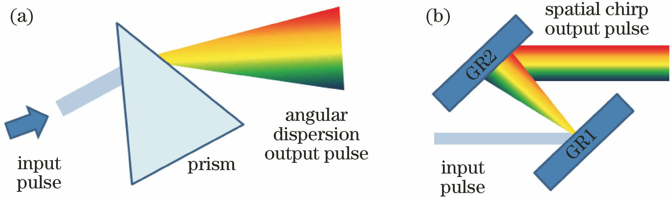
Fig. 1. Introduction of AD and SC. (a) Prism; (b) grating
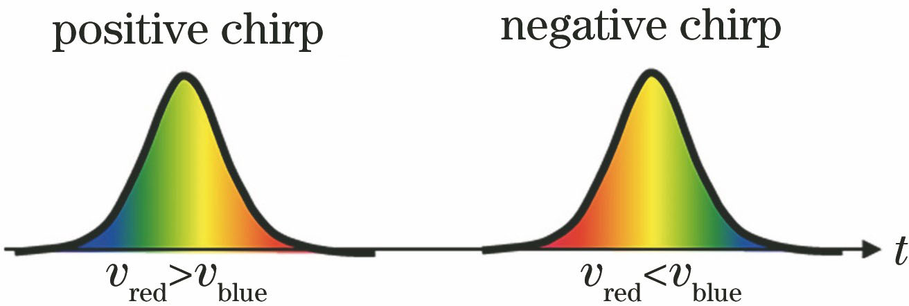
Fig. 2. Temporal chirp
Fig. 3. Two sources of pulse-front tilt. (a) Angular dispersion; (b) combination of spatial and temporal chirp[49]
Fig. 4. Principle of femtosecond laser SSTF technology[56]
Fig. 5. Comparison of nonlinear effect at different areas between common focusing and spatio-temporal focusing conditions. (a) Without spatially chirped pulses, self-focusing and supercontinuum generation result in a loss of intensity at the focus; (b) with spatially chirped pulses, self-focusing and continuum generation are suppressed[28]
Fig. 6. Image of 2 mm height lion sculpture. (a) SEM image in the front view of sculpture; (b) front view of the original model; (c) SEM image of the head of fabricated lion; (d) head of the original model exhibited from the same angle of view[60]
Fig. 7. Schematic of four-dimensional optical shaping. (a) Optical experimental setup; (b) relationship between conventional focus and SSTF, as well as single focus and holographic 3D multiplexed[44]
Fig. 8. Nonreciprocal direct writing phenomenon. (a) Orthogonal polarization and differential interference images of the lines written with orthogonal polarizations; (b) SEM images of cross sections of lines written with polarization perpendicular to writing direction[32]
Fig. 9. Glass modification under the influence of PFT. (a) Orientation of the pulse front tilt at the focal plane (dashed line);blue arrow is the writing direction, E is the polarization direction, in Fig. (b)-(d), each set of anti-parallel lines was imaged with bright field (top) and cross-polarized illumination (bottom); scale bar is 50 μm[33]
Fig. 10. Dependence of orientation of induced nanogating on PFT of femtosecond laser. (a) SEM images of self-organized nanogratings in transversal cross-section of the written lines with varied polarization plane azimuth(red curve highlights the varying trend for the longitudinal length of nanogratings); (b) SEM images of the written nanogratings in the transversal cross-section with two opposite scan directions; (c) schematic of 3D rotation of nanogratings[62]
Fig. 11. Asymmetric microstructures induced by spatially chirped pulse in fused silica. (a)(c) Optical images of transverse sections of the asymmetric microstructures with tilted heads induced by the laser pulses; corresponding to the processing diagram (b) without a Dove prism and (d) with a Dove prism[39]
Fig. 12. Different laser fluence distributions at the focus with varied coupling parameters. (a)(c)(e) Coupling parameter, respectively p=(14+0.7i) fs/μm, p=(0.2+2i) fs/μm, and p=(-13.8-3.7i)fs/μm; (b)(d)(f) corresponding control group[52]

Set citation alerts for the article
Please enter your email address
© Copyright 2018-2021 | Chinese Laser Press. All Rights Reserved 沪ICP备15018463号-20