• Infrared and Laser Engineering
  • Vol. 50, Issue 5, 20200397 (2021)
Youdao Gao1, Fudong Li1, Zhengxiang Shen2, Lin Ding1, Bin Hu1, and Shaowei Xu1
Author Affiliations
  • 1Beijing Institute of Space Mechanics & Electricity, Beijing 100094, China
  • 2School of Physical Science and Engineering, Tongji University, Shanghai 200092, China
  • show less
    DOI: 10.3788/IRLA20200397 Cite this Article
    Youdao Gao, Fudong Li, Zhengxiang Shen, Lin Ding, Bin Hu, Shaowei Xu. Simulation method and its test verification of cryogenic infrared lens design[J]. Infrared and Laser Engineering, 2021, 50(5): 20200397 Copy Citation Text show less
    Design scheme of cryogenic lens shows
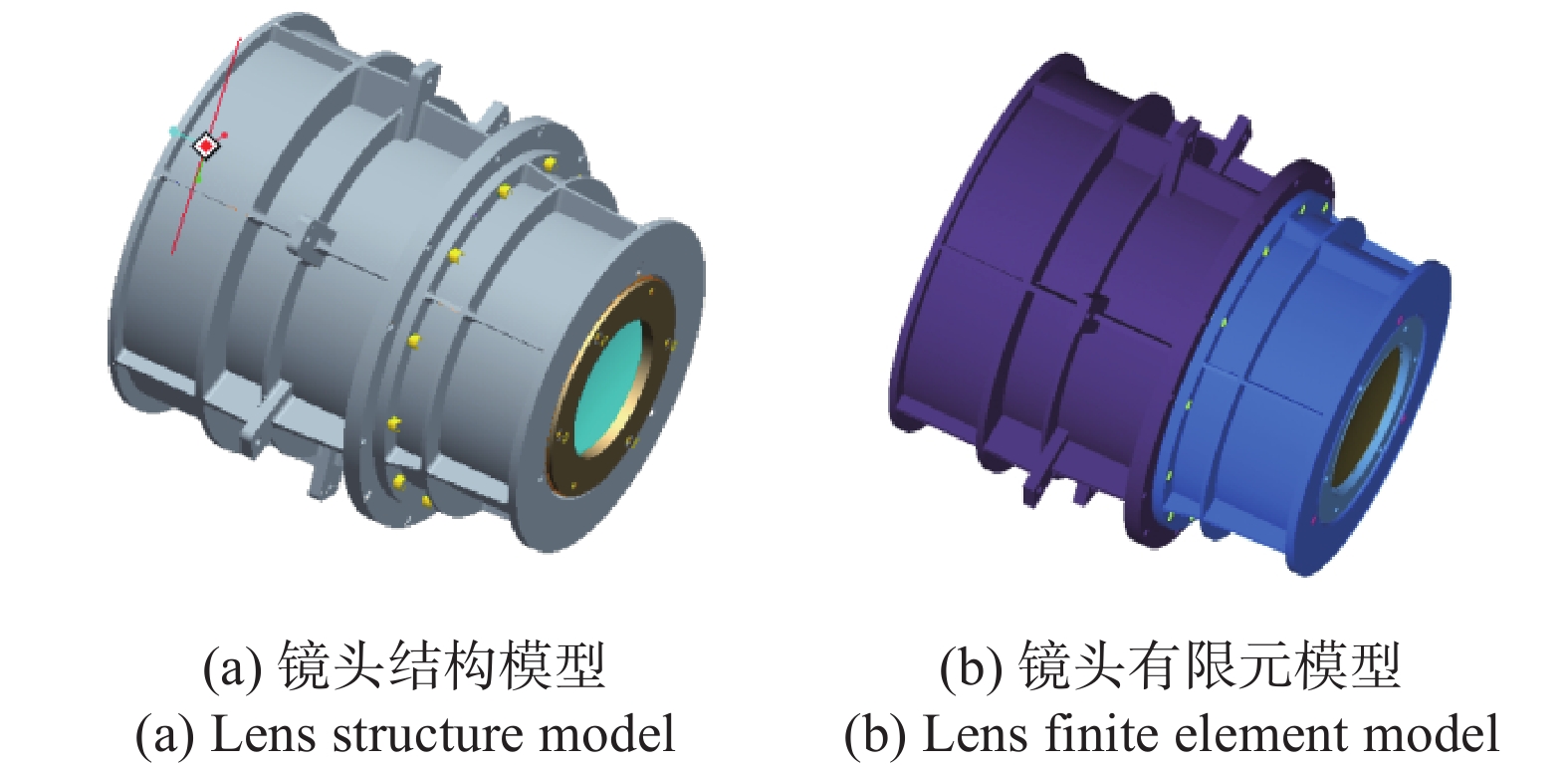
    Fig. 1. Design scheme of cryogenic lens shows
    Nephogram of displacement distribution of lens nodes
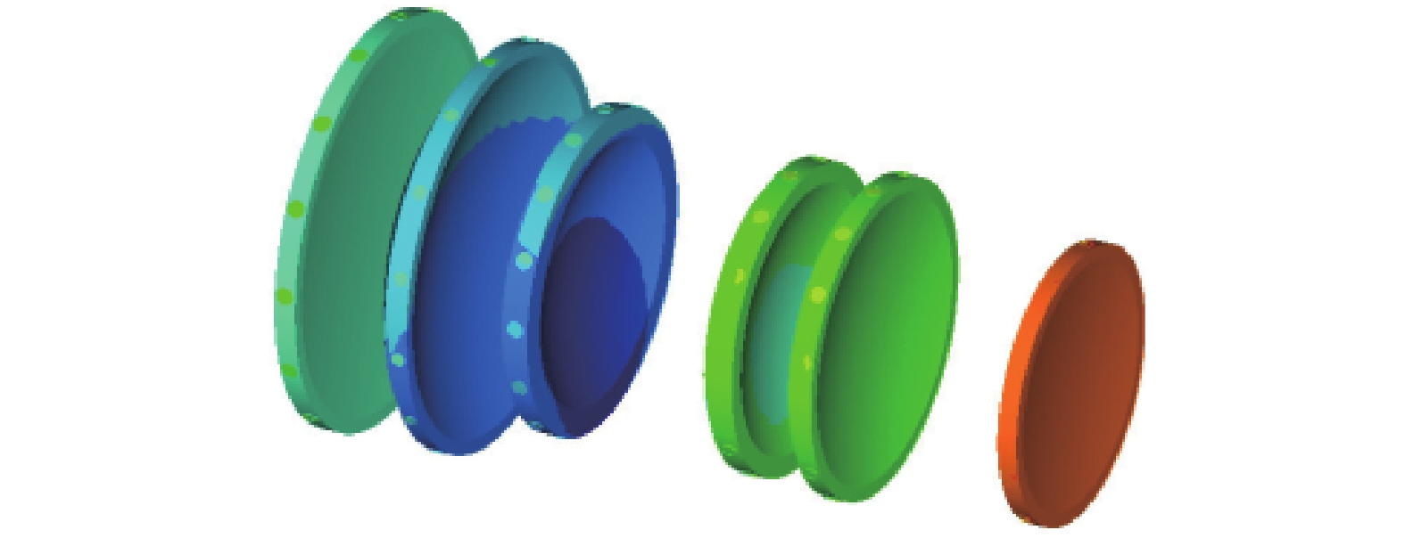
    Fig. 2. Nephogram of displacement distribution of lens nodes
    Surface shape diagram of lens 2 (removing rigid body displacement)
    Fig. 3. Surface shape diagram of lens 2 (removing rigid body displacement)
    MTF curve of optical system
    Fig. 4. MTF curve of optical system
    Schematic diagram of test product composition
    Fig. 5. Schematic diagram of test product composition
    Schematic diagram of tank preparation
    Fig. 6. Schematic diagram of tank preparation
    MTF test diagram
    Fig. 7. MTF test diagram
    Mirror numberTxTyTzRxRyRz
    11−2.7949E-049.9660E-03−6.0877E-027.1514E-06−1.5074E-06−5.8983E-07
    12−8.1982E-049.3528E-03−5.6416E-027.0429E-06−1.5240E-06−5.8931E-07
    21−3.9439E-041.2825E-02−3.4461E-021.4481E-05−2.0520E-06−7.9392E-07
    221.6542E-051.3727E-02−2.8960E-021.3445E-05−3.9253E-06−7.9809E-07
    313.8012E-041.1789E-02−6.2370E-03−2.1042E-07−1.6917E-06−7.8651E-07
    32−4.8088E-051.1473E-02−1.9305E-03−7.3894E-07−2.7398E-06−7.9127E-07
    41−7.1167E-051.1914E-025.8549E-021.1449E-05−1.3130E-06−3.1968E-07
    42−9.3400E-041.2348E-026.3718E-021.1444E-05−2.6384E-06−3.2117E-07
    513.9997E-051.1358E-026.3480E-021.6506E-05−9.3102E-07−4.2036E-07
    52−1.0513E-031.1771E-027.0715E-021.5050E-05−4.2598E-06−4.1898E-07
    61−1.1529E-031.2242E-021.1839E-018.7089E-06−4.1861E-06−1.6503E-07
    62−9.5614E-041.2250E-021.2138E-018.9706E-06−3.0556E-06−1.6429E-07
    Table 1. Rigid body displacement of lens
    Zernike numberLens 1 first sideLens 1 second side
    1−0.00039554−0.00019119
    2−0.001655450.00129153
    30.0006715−0.0053511
    40.00052970.0011647
    50.04891640.055137
    370.00015646−0.00004436
    Table 2. Zernike coefficients of lens 2 fitted at 210 K
    CategoryDefocusing amount/μm
    Theoretical design73.56
    210 K fitting70.189
    Table 3. Defocus of optical system
    Working conditionMTFDefocusing amount/μm
    Theoretical design (210 K)0.6586 (Cryogenic lens)73.56
    Simulation fitting (210 K)0.6324 (Cryogenic lens)70.189
    Room temperature test (293 K)0.2861 (System)
    Low temperature test (210 K)0.2854 (System)71.2
    Table 4. Theoretical design, fitting simulation and test results
    Youdao Gao, Fudong Li, Zhengxiang Shen, Lin Ding, Bin Hu, Shaowei Xu. Simulation method and its test verification of cryogenic infrared lens design[J]. Infrared and Laser Engineering, 2021, 50(5): 20200397
    Download Citation