• Laser & Optoelectronics Progress
  • Vol. 57, Issue 1, 010003 (2020)
Yanyan Zhou1, Yongchuan Xiao2, Lijun Sun2, Yang Chen1, Shibiao Liao1, Qiang Qiu1, Zhimu Gu1, Nengli Dai1、*, and Jinyan Li1
Author Affiliations
  • 1Wuhan National Laboratory for Optoelectronic, Huazhong University of Science and Technology, Wuhan, Hubei 430074, China
  • 2Chongqing Optoelectronics Research Institute, Nanping, Chongqing 400060, China
  • show less
    DOI: 10.3788/LOP57.010003 Cite this Article Set citation alerts
    Yanyan Zhou, Yongchuan Xiao, Lijun Sun, Yang Chen, Shibiao Liao, Qiang Qiu, Zhimu Gu, Nengli Dai, Jinyan Li. Optical-Fiber Fluorescent Probes[J]. Laser & Optoelectronics Progress, 2020, 57(1): 010003 Copy Citation Text show less
    Typical system diagram of opitcal-fiber fluorescent probe
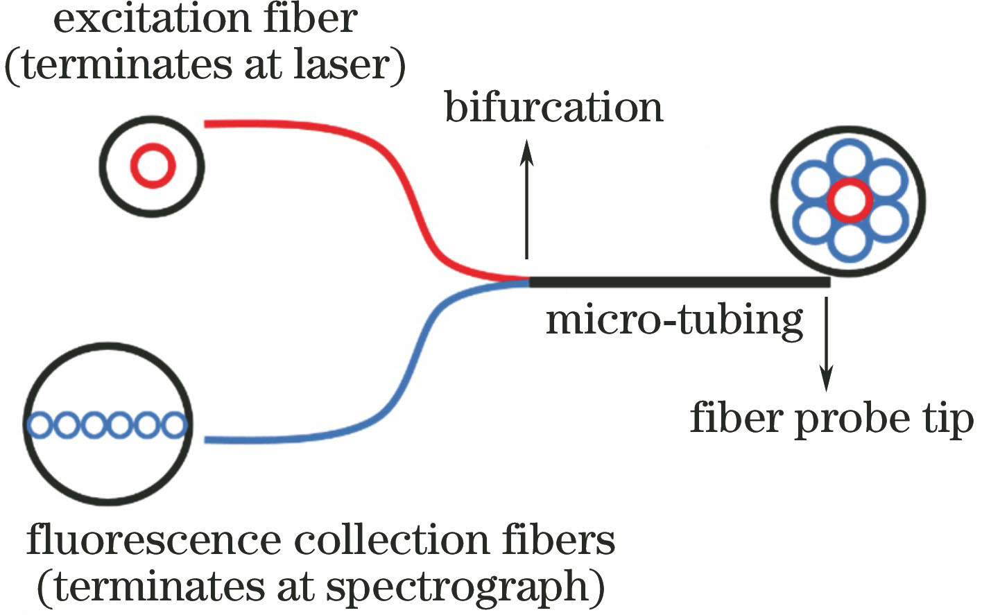
    Fig. 1. Typical system diagram of opitcal-fiber fluorescent probe
    Flat-head probe structure consisting of two fibers with identical diameters
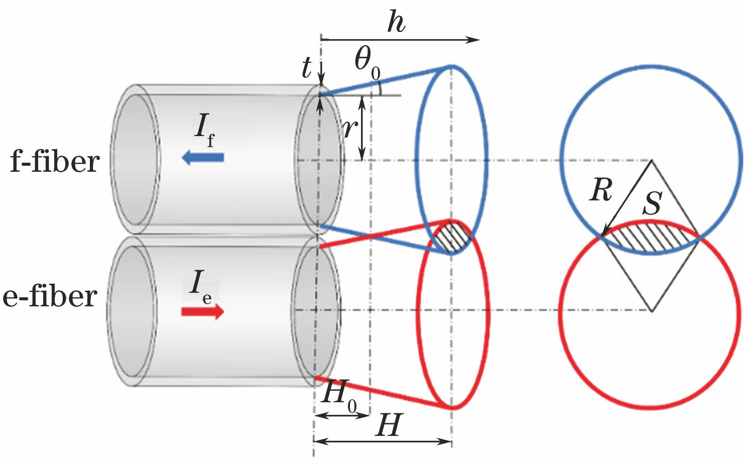
    Fig. 2. Flat-head probe structure consisting of two fibers with identical diameters
    Flat-head probe structure consisting of seven fibers with identical diameters. (a) Structural model; (b) micrograph of probe
    Fig. 3. Flat-head probe structure consisting of seven fibers with identical diameters. (a) Structural model; (b) micrograph of probe
    Structure of optical-fiber probe and fluorescence spectroscopy system
    Fig. 4. Structure of optical-fiber probe and fluorescence spectroscopy system
    Structure of multipixel opitcal-fiber probe. (a) Model diagram of end-face structure; (b) micrograph of probe[27]
    Fig. 5. Structure of multipixel opitcal-fiber probe. (a) Model diagram of end-face structure; (b) micrograph of probe[27]
    Fluorescence spectroscopy system based on single double-clad optical-fiber probe
    Fig. 6. Fluorescence spectroscopy system based on single double-clad optical-fiber probe
    Scanning electron micrographs of large-mode-field double-clad photonic crystal fiber[29]
    Fig. 7. Scanning electron micrographs of large-mode-field double-clad photonic crystal fiber[29]
    Preparation of cone-column optical-fiber fluorescent probe by using tube etching
    Fig. 8. Preparation of cone-column optical-fiber fluorescent probe by using tube etching
    Principle of cone-column optical-fiber probe for evanescent-wave sensing
    Fig. 9. Principle of cone-column optical-fiber probe for evanescent-wave sensing
    Fiber-optic scanning two-photon fluorescence endoscope. (a) Cross-section of double-clad optical-fiber probe; (b) principle of optical-fiber scanning two-photon fluorescence endoscope imaging system[46]
    Fig. 10. Fiber-optic scanning two-photon fluorescence endoscope. (a) Cross-section of double-clad optical-fiber probe; (b) principle of optical-fiber scanning two-photon fluorescence endoscope imaging system[46]
    Two-photon fluorescence images obtained by scanning groups of neurons inside brain of Thy1-EGFP mouse by optical-fiber probe can enable a quantitative assessment of mechanical effects caused by laser scanning on neurons[53]. (a)-(c) Field of displacements of individual neurons (whose changing positions are labeled by circles 1-4) scanned by optical-fiber probe (red); (d) close-up view of normal neurons; (e) close-up view of distorted neurons
    Fig. 11. Two-photon fluorescence images obtained by scanning groups of neurons inside brain of Thy1-EGFP mouse by optical-fiber probe can enable a quantitative assessment of mechanical effects caused by laser scanning on neurons[53]. (a)-(c) Field of displacements of individual neurons (whose changing positions are labeled by circles 1-4) scanned by optical-fiber probe (red); (d) close-up view of normal neurons; (e) close-up view of distorted neurons
    Comparison between acute and chronic diagnosis[54]. (a) Schematic of acute diagnosis; (b) schematic of chronic diagnosis
    Fig. 12. Comparison between acute and chronic diagnosis[54]. (a) Schematic of acute diagnosis; (b) schematic of chronic diagnosis
    Optical-fiber-probe-based fluorescence measurement system for pesticide detection in soil[56]. (a) Overview of measurement system; (b) taper-shaped aiguille
    Fig. 13. Optical-fiber-probe-based fluorescence measurement system for pesticide detection in soil[56]. (a) Overview of measurement system; (b) taper-shaped aiguille
    Yanyan Zhou, Yongchuan Xiao, Lijun Sun, Yang Chen, Shibiao Liao, Qiang Qiu, Zhimu Gu, Nengli Dai, Jinyan Li. Optical-Fiber Fluorescent Probes[J]. Laser & Optoelectronics Progress, 2020, 57(1): 010003
    Download Citation