• Photonics Research
  • Vol. 7, Issue 2, 110 (2019)
Lu Xu1, Jie Hou1, Haitao Tang1, Yuan Yu1、2、3、*, Yu Yu1、2、4、*, Xuewen Shu1、2, and Xinliang Zhang1、2
Author Affiliations
  • 1Wuhan National Laboratory for Optoelectronics, Huazhong University of Science and Technology, Wuhan 430074, China
  • 2School of Optical and Electrical Information, Huazhong University of Science and Technology, Wuhan 430074, China
  • 3e-mail: yuan_yu@hust.edu.cn
  • 4e-mail: yuyu@mail.hust.edu.cn
  • show less
    DOI: 10.1364/PRJ.7.000110 Cite this Article Set citation alerts
    Lu Xu, Jie Hou, Haitao Tang, Yuan Yu, Yu Yu, Xuewen Shu, Xinliang Zhang. Silicon-on-insulator-based microwave photonic filter with widely adjustable bandwidth[J]. Photonics Research, 2019, 7(2): 110 Copy Citation Text show less
    Optical spectra of the phase-modulated signal and the flattop optical filter when the frequency of the optical carrier is tuned (a) aligned with the center of the optical filter and (b) away from the center of the optical filter.
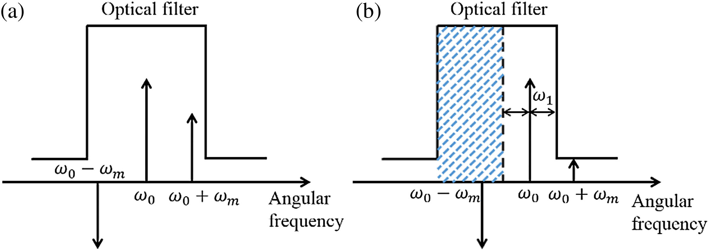
    Fig. 1. Optical spectra of the phase-modulated signal and the flattop optical filter when the frequency of the optical carrier is tuned (a) aligned with the center of the optical filter and (b) away from the center of the optical filter.
    Structure of the photonic chip.
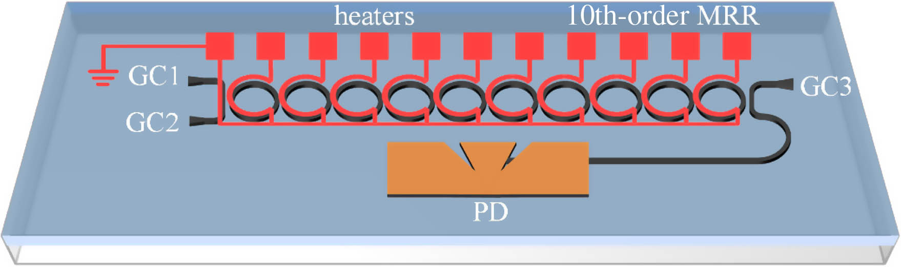
    Fig. 2. Structure of the photonic chip.
    Simulated results of (a) output at the drop port of the 10th-order MRR and (b) proposed MPF with adjustable bandwidths.
    Fig. 3. Simulated results of (a) output at the drop port of the 10th-order MRR and (b) proposed MPF with adjustable bandwidths.
    Optical micrograph of the fabricated device.
    Fig. 4. Optical micrograph of the fabricated device.
    Experimental setup of tuning the 10th-order MRR. BOS, broadband optical source; PBS, polarization beam splitter; PC, polarization controller; OSA, optical spectrum analyzer.
    Fig. 5. Experimental setup of tuning the 10th-order MRR. BOS, broadband optical source; PBS, polarization beam splitter; PC, polarization controller; OSA, optical spectrum analyzer.
    Optimized optical filter at the drop port.
    Fig. 6. Optimized optical filter at the drop port.
    Experimental setup of the proposed MPF. LD, laser diode; PC, polarization controller; PM, phase modulator; EA, electronic amplifier; VNA, vector network analyzer.
    Fig. 7. Experimental setup of the proposed MPF. LD, laser diode; PC, polarization controller; PM, phase modulator; EA, electronic amplifier; VNA, vector network analyzer.
    (a) Measured dark current of the Ge PD; (b) measured response of the Ge PD.
    Fig. 8. (a) Measured dark current of the Ge PD; (b) measured response of the Ge PD.
    Optical spectra of the bandpass filter and the phase-modulated signals after the filter.
    Fig. 9. Optical spectra of the bandpass filter and the phase-modulated signals after the filter.
    Measured frequency responses of the proposed MPF with different bandwidths.
    Fig. 10. Measured frequency responses of the proposed MPF with different bandwidths.
    Lu Xu, Jie Hou, Haitao Tang, Yuan Yu, Yu Yu, Xuewen Shu, Xinliang Zhang. Silicon-on-insulator-based microwave photonic filter with widely adjustable bandwidth[J]. Photonics Research, 2019, 7(2): 110
    Download Citation