
Heming Wei, Zhangli Wu, Kexuan Sun, Haiyan Zhang, Chen Wang, Kemin Wang, Tian Yang, Fufei Pang, Xiaobei Zhang, Tingyun Wang, Sridhar Krishnaswamy, "Two-photon 3D printed spring-based Fabry–Pérot cavity resonator for acoustic wave detection and imaging," Photonics Res. 11, 780 (2023)
- Photonics Research
- Vol. 11, Issue 5, 780 (2023)
Abstract
1. INTRODUCTION
Acoustic wave-based sensing and imaging methods have been widely studied in various important applications such as biomedical imaging and underwater safety monitoring [1–3]. The key role in such applications is to develop acoustic/ultrasonic sensors exhibiting high sensitivity, broad bandwidth, and high frequency response. Typically, piezoelectric-based sensors and transducers are used because they can respond to high-frequency acoustic waves with ultrahigh sensitivity and relatively high bandwidth. However, electrical transmission from the sensing elements to the detection at high frequencies could be noisy, and fabrication could be problematic at a very high response frequency. In view of these limitations, there are alternatives based on optical sensors, especially fiber optic sensors such as fiber Bragg gratings (FBGs) [4,5], fiber Fabry–Pérot interferometers (FPIs) [6–8], fiber Michelson interferometers (MIs) [9,10], fiber Mach–Zehnder interferometers (MZIs) [11,12] and Sagnac interferometers (SIs) [13,14]. These options all offer attractive advantages, including immunity to electromagnetic interference and a compact size, which could be very interesting for acoustic sensing and imaging. Compared to other fiber-optic acoustic sensors, FPI microresonators can be miniaturized as a fiber probe by easy fabrication approaches and can exhibit high sensitivity [15–18]. The basic principle of FPI-based acoustic sensors is the vibration of the thin diaphragm that modulates the cavity spacing, and the elasto-optical effect that modulates the cavity refractive index. However, the stiffness of the silica could be a fundamental limitation for acoustic wave-induced strain sensing.
To overcome this issue, various methods ranging from functional materials to novel structures have been proposed and demonstrated for highly sensitive acoustic wave sensing. For diaphragm-based FP sensors, polymer-based functional materials with a high-elastic property have been used to design highly sensitive FP acoustic sensors [15,16]. To further increase the sensitivity, 2D materials have been proposed for highly sensitive acoustic sensing because the diaphragms can be extra thin [17–19]. However, fabrication of such sensors is complicated and prone to variability from sensor to sensor. An alternative is to design flexible structures [20–22] such as corrugated structure microsprings, which show flexibility and low stiffness and can significantly enhance the sensitivity. To further improve this interaction, Yao
In this work, we propose what we believe, to the best of our knowledge, is a novel optomechanical resonator for acoustic wave sensing and imaging. The device consists of one thin diaphragm connected to several springs that act as the supports, all of which are directly 3D printed on an optical fiber tip through two-photon polymerization. The resonant frequency is optimized to investigate the mode coupling between the plate and spring vibrations. Several high-order plate-domain vibration modes are found within the range from 0 to 3 MHz, which can be determined by the spring vibration mode or the point-clamped circular plate vibration mode. The experiments show that the device exhibits a high sensitivity that can detect weak acoustic waves.
Sign up for Photonics Research TOC. Get the latest issue of Photonics Research delivered right to you!Sign up now
2. MODEL DESIGN AND SIMULATION
Figure 1 shows the proposed FP cavity resonator, which consists of several springs as the supports. According to the mechanical vibration theory, the spring has a resonant frequency given by [24]
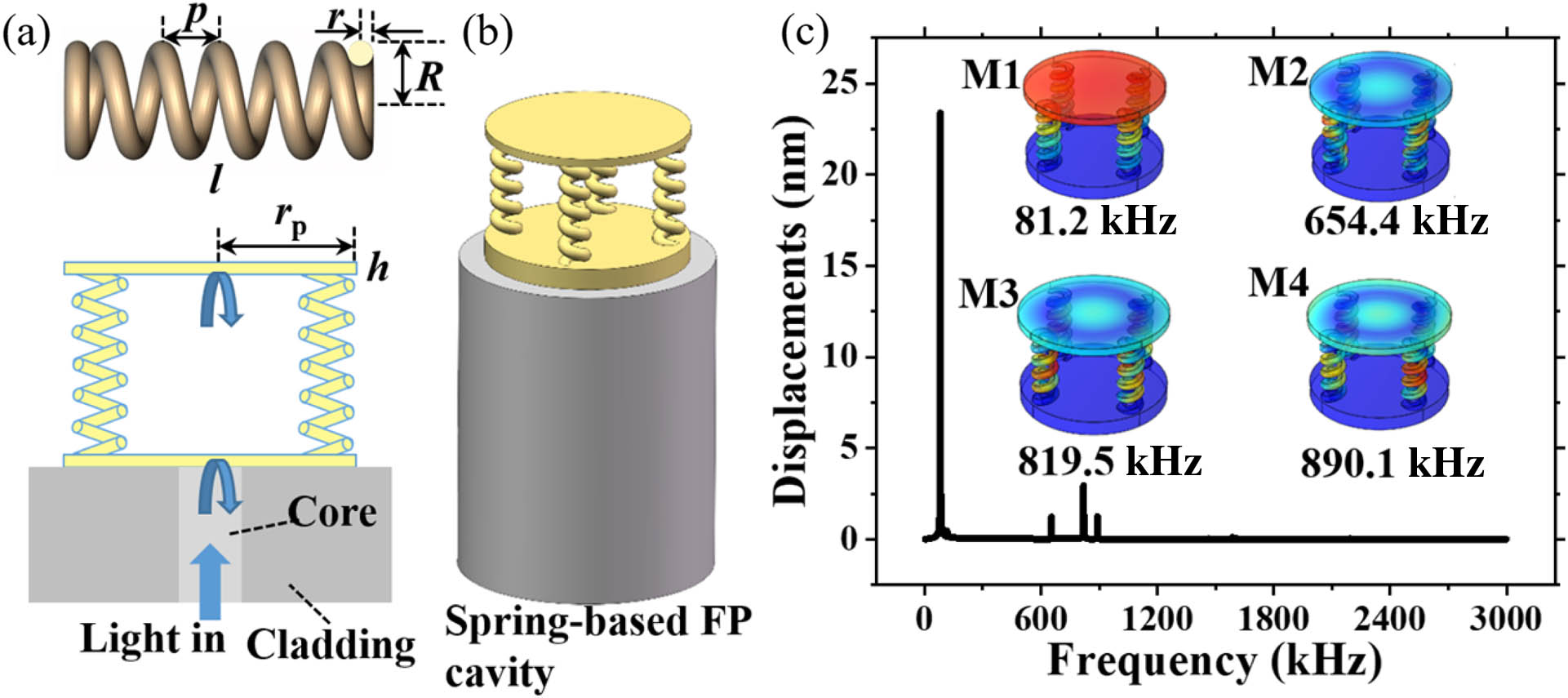
Figure 1.Proposed spring-based FP optomechanical cavity resonator. (a) Schematic diagram of the spring resonator and the fiber-tip-based FP cavity where the springs are used as the supports with low stiffness. (b) Schematic diagram of the proposed FP cavity microresonator for acoustic wave detection and imaging. (c) Mode simulation of the proposed device used for acoustic wave sensing in a water environment. Four vibration modes are found within the range from 0 to 3 MHz when the parameters are initially set as
Figure 2 shows a simulation of the vibration modes of each part and the system. Here, the radius and thickness of the plate are set as 50 μm and 1 μm. It can be seen from Fig. 2(a) that the resonant frequency of the spring decreases while the resonant frequency of the plate increases as the outer radius increases. For the whole device, the frequency decreases due to the mode coupling between the springs and plate. Note that the stiffness will be high if the wire radius increases, and the resonant frequencies of the spring increase, while the frequency of the plate membrane slightly increases due to the increasing connections; hence, the resonant frequency of the whole device increases, as shown in Fig. 2(b). Note that the support conditions change as the outer radius and the wire radius change, which causes the resonant frequency of the plate membrane to also change.
![]()
Figure 2.Resonant frequency behavior of the whole device and its individual parts related to the parameters of (a) the outer radius, (b) the wire radius, (c) the coil number, and (d) the pitch. In these simulations, the resonant frequency of an individual part is studied assuming that the other part is rigidly constrained.
In addition, the effect of the coil number and pitch was investigated. It was found that the frequency of the spring decreases as the coil number increases while the frequency of the plate membrane is almost unchanged. Therefore, the resonant frequency is then decreased, as shown in Fig. 2(c). The frequencies of the device do not change significantly when the pitch changes, as shown in Fig. 2(d). It is interesting to see that the frequency spectrum can be divided into three regions: a spring-dominated area, a plate-dominated area, and a maximal coupling area. Based on the frequency spectrum, each device with different domain-vibration modes can be designed for acoustic wave detection.
The stiffness of the springs does not change significantly as the plate thickness changes while the resonant frequency of the plate significantly increases as the thickness increases, as shown in Fig. 3. Figure 3(a) shows the frequency versus the thickness of the membrane when the outer radius, the wire radius, the pitch, and the coil number are, respectively, 9 μm, 3 μm, 10 μm, and 5. The three regions are still found when the membrane thickness changes, as shown in Fig. 3(b). As the frequency of the plate membrane is significantly larger than that of the spring, the resonant frequency of the device is almost unchanged, which is mainly determined by the springs.
![]()
Figure 3.Resonant frequency behavior of the device system and each part versus the plate membrane related to the parameters of the thickness within a range from (a) 0.5 to 10 μm and (b) 0.5 to 3 μm, where the outer radius is 9 μm and 7 μm.
3. FABRICATION AND CHARACTERIZATION
A. Fabrication
Based on the simulation results, the spring-dominant FP optomechanical cavity was designed and then fabricated using a direct laser writing technique through two-photon polymerization. First, a piece of single-mode fiber was cleaved and mounted by a fiber holder and immersed into a droplet of photoresist (IP-Dip, Nanoscribe), which was prepared on a
First, two devices with different cavity lengths of 50 and 140 μm were printed. The springs have an outer radius of 9 μm, a wire radius of 3 μm, a coil number of 5, and a pitch of 10 μm, and the plate has a thickness of 5 μm and a radius of 50 μm. Figures 4(a) and 4(b) show scanning electron images and microscopic images of the devices with different cavity lengths. Figures 4(c) and 4(d) show the normalized reflected spectra of the devices in atmospheric and aquatic environments. It can be seen that the reflection in water decreases; however, the fringe contrast slightly increases. Sample 2 (S2) has a large fringe contrast of 30 dB, which is much higher than the reported 3D printed FP devices. Here, the FP device with a longer cavity shows the comparable reflections from the fiber tip and diaphragm, which leads to a high fringe contrast. Note that the sensitivity is related to this value. Therefore, for the following experiments, FPs with long cavities are used for acoustic wave sensing. Note that the supporting pillars can be vibrated, which can then change the device’s resonant frequency. Therefore, the size of supporting pillar is designed to be large enough to avoid coupling.
![]()
Figure 4.Results of the 3D-printed devices. (a) Scanning electron images and (b) microscopic images of the fabricated microresonators. (c) and (d) Reflection spectra of the devices in atmospheric and aquatic environments.
To further investigate the fiber-tip-based, two-photon 3D fabrication, a few FP devices are fabricated. Since parameters such as the outer radius, wire radius, coil number, and pitch are used to tune the spring resonance behavior, different outer radii are chosen for fabrication of spring-tuning structures, as shown in Fig. 5. The top side of each figure in Fig. 5 shows the microscopic image of the fabricated device. The bottom sides of Figs. 5(a), 5(b), and 5(c) show the reflections of spring-tuning devices with different outer radii of 7 μm, 9 μm, and 11 μm, respectively, when the diaphragm thickness is 5 μm. Figures 5(d)–5(f) show the reflections of the devices with different outer radii when the diaphragm thickness is 1 μm. It can be seen that the devices immersed into water show additional loss. Due to the fabrication issues, some of the fringe contrasts are smaller. Here, the device with a highest fringe contrast [Fig. 5(b)] is used for acoustic wave sensing.
![]()
Figure 5.Reflection spectra of the devices in atmospheric and aquatic environments. (a)–(c) Devices with a diaphragm thickness of 5 μm and an outer radius of (a) 7 μm, (b) 9 μm, and (c) 11 μm. (d)–(f) Devices with a diaphragm thickness of 1 μm and an outer radius of (d) 7 μm, (e) 9 μm, and (f) 11 μm.
B. Ultrasound Detection
Based on the investigation of this FP cavity resonator, any stimulus on the plate will cause a vibration of the device and then lead to a change in phase. Here, the device is characterized for acoustic wave detection. To evaluate the response of the proposed FP microdevice, ultrasonic waves were generated using piezoelectric ultrasonic transducers driven by a function generator or pulser/receiver (DPR300, JSR Corp. Tokyo). The experimental setup is shown in Fig. 6, where a tunable laser (TUNICS T100S-HP, EXFO, Quebec City, Quebec, Canada) was used as the light source. The light transmitted through a circulator and was reflected by the device and detected by a photodetector connecting a digital oscilloscope. To characterize the input acoustic wave pressure, a commercial hydrophone [8104, Hottinger Brüel & Kjær A/S (HBK), Virum, Denmark] was used. All the driver and sensors were immersed into a water tank. To obtain a maximal sensitivity, the laser wavelength was locked at the quadrature point.
![]()
Figure 6.Schematic diagram of the experimental setup for acoustic wave detection.
First, the low frequency response of the device was investigated, as shown in Fig. 7. In the measurements, the acoustic wave was generated by a broadband ultrasonic transducer (UT) with a central response frequency of 80 kHz. Figures 7(a) and 7(b) show the time and frequency responses of the fabricated device. The device had a peak frequency response at 83.9 kHz, which is very close to the simulation. To further investigate the noise equivalent acoustic signal level, a sinusoidal burst signal was generated, as shown in Fig. 7(c), where the amplitude was about 82.5 Pa and the frequency was 75 kHz. The inset of Fig. 7(c) shows the detected time response, and the frequency response shows a high SNR of 56.2 dB, which converts a noise equivalent acoustic signal level of
![]()
Figure 7.Low frequency response of the device: (a) time response and (b) frequency response. (c) Acoustic response of the device to the sinusoidal burst signal with an amplitude of 82.5 Pa and a frequency of 75 kHz. The inset shows the detected time response.
Next, we investigated the high-frequency response of the device to sinusoidal acoustic waves with a frequency of 750 kHz by driving the UT with a burst sinusoidal electric signal. High frequency modes near 800 kHz were obtained, as shown in Fig. 8(a), which is very close to the simulated results. Next, the sensitivity of acoustic wave pressure was characterized, as shown in Fig. 8(b). A continuous sinusoidal wave with a frequency of 750 kHz was generated. The detected signals with different input voltages were obtained, as shown in the inset of Fig. 8(b). It can be seen that the detected output varies linearly with the amplitude of the input signal. The slope is calculated as 0.0883 mV/Vpp, which converts into a displacement sensitivity of 22.4 nm/kPa. Additionally, the angle response of the device also was investigated. Just like the sensitivity experiment, a continuous sinusoidal wave with a frequency of 750 kHz was generated. The calculated amplitude of the detected signals versus the testing angle is shown in Fig. 8(c), where the inset shows the testing setup. It can be seen that device has relatively broad angular response, making the FP-based microresonator an ideal directional point detector for imaging applications.
![]()
Figure 8.(a) High acoustic response of the device to the sinusoidal burst signal. The inset shows a detected time signal at 750 kHz. (b) Acoustic wave pressure sensitivity and (c) angle response of the device.
C. Ultrasound Imaging
Optical fiber-based ultrasound imaging has received considerable attention in the last decades [28–30]. As well as high sensitivity, typically a well-behaved frequency response is important, which is sufficiently broadband to capture all relevant frequencies in an acoustic pulse signal. However, for microresonators, the resonating frequency is usually used as the sensitivity because the frequency is much higher. Here, we pick a nonresonant frequency as the sound source for data analysis. To demonstrate the practical applicability of ultrasound imaging, the fabricated device was used for underwater positioning and imaging, as shown in Fig. 9.
![]()
Figure 9.(a) Schematic of the experimental setup. (b) Total focusing algorithm. (c) Detected signals at different detecting positions. (d) Reconstructed cross-section image of the objects.
Figure 9(a) shows the schematic of the acoustic wave position and imaging measurement setup using the FP microresonator. The acoustic signal was generated by a water immersion UT (Olympus C306, 2.25 MHz central frequency, Evident Corp., Tokyo) connecting a pulser (DPR300, 35 MHz bandwidth, JSR). Three steel pillars with a distance of a few millimeters were mounted under water. To realize the object positioning, the proposed FP acoustic device was used as a moving detector based on an ultrasonic total focusing method [31–33]. In this work, the UT was fixed at a position with a certain angle. The generated acoustic signal was reflected by the objects and detected by the fiber tip FP device, which was immersed into water and linearly scanned. Figure 9(b) illustrates the algorithm for the target positioning and imaging. The reflected information can be obtained at each specific phase based on this algorithm. Figure 9(c) shows a series of raw detected signals with no time averaging. It is clear that the reflected signal contains three strong peaks. According to the total focusing algorithm, the three targets with millimeter scale can be detected and the reconstructed cross-section image, as shown in Fig. 9(d), agrees well with the value set in the experiment. This demonstrates that the proposed fiber tip device can be used for high-resolution objective positioning and imaging.
4. CONCLUSION
In this work, we proposed what we believe, to the best of our knowledge, is a novel spring-based FP cavity microresonator, designed, fabricated, and used for acoustic wave detection and imaging. Two vibration modes of the resonator were observed. We found that the vibration modes can be coupled and optimized by changing the structure size. Compared to other reported micro-optomechanical FP cavities, the spring-based FP resonator exhibits a high ultrasound sensitivity, which can be used for underwater object imaging. It demonstrates that the proposed work has great potential in acoustic detection and biomedical imaging applications. To obtain a higher sensitivity, the optical performance of the device can be further improved by optimizing the fabrication issues. For high-resolution imaging, a sensor array can be designed in the future.
References


Set citation alerts for the article
Please enter your email address

© Copyright 2018-2021 | Chinese Laser Press. All Rights Reserved 沪ICP备15018463号-20