
Yunlong Zhang, Shufeng Sun, Xi Wang, Fengyun Zhang, Li Liu, Shiguang Liu. Research on Quality of Micro-Holes Fabricated by Laser Drilling[J]. Laser & Optoelectronics Progress, 2021, 58(19): 1900002
- Laser & Optoelectronics Progress
- Vol. 58, Issue 19, 1900002 (2021)
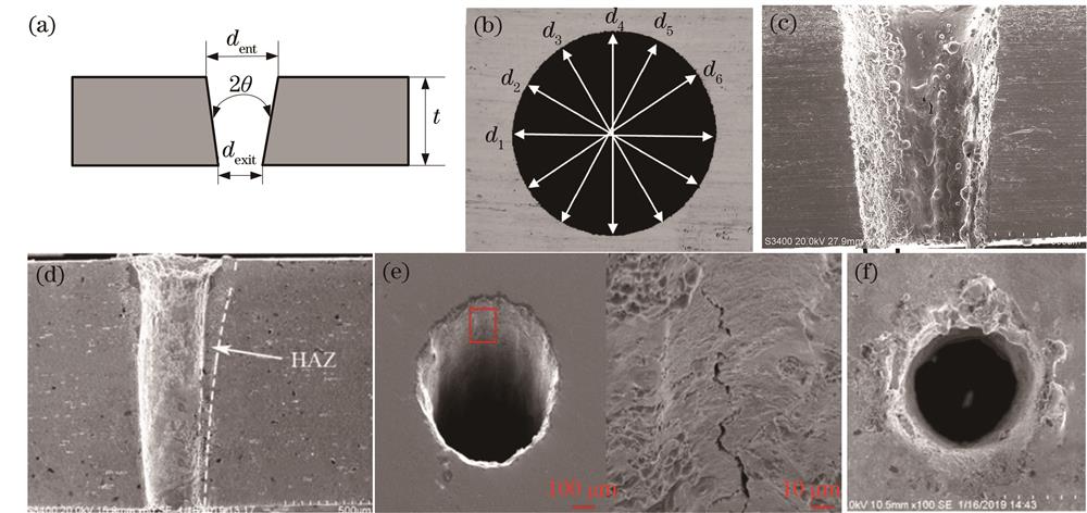
Fig. 1. Schematic diagrams of micropore quality characteristics. (a) Taper; (b) roundness; (c) recast layer; (d) heat-affected zone; (e) microcracks; (f) spatter deposition around periphery of holes
![Influence of pulse width on quality of micro-holes[47-48]. (a) Relationship between pulse width and hole diameter; (b) relationship between pulse width and hole depth; (c) micro-hole morphologies under different pulse widths](/richHtml/lop/2021/58/19/1900002/img_2.jpg)
Fig. 2. Influence of pulse width on quality of micro-holes[47-48]. (a) Relationship between pulse width and hole diameter; (b) relationship between pulse width and hole depth; (c) micro-hole morphologies under different pulse widths
Fig. 3. Effect of repetition frequency on quality of micro-holes[51-53,55]. (a) Relationship between repetition frequency and diameter of micro-holes; (b) relationship between repetition frequency and depth of micro-holes; (c) relationship among repetition frequency, taper, and heat-affected zone; (d) effect of repetition frequency on roundness of micro-shallow holes
Fig. 4. Influence of laser energy on quality of micro-holes[57-58,60]. (a) Relationship between laser energy and taper; (b) images of entrance and exit of micro-holes under different power; (c) relationship between laser power and roughness of micro-hole
Fig. 5. Influence of focal position on quality of micro-holes[63-64]. (a) Relationship between focus position and hole taper; (b) relationship between focus position and splash area
Fig. 6. Effect of laser wavelength on quality of micro-holes[67-68]. (a) Micro-hole section view obtained by 532 nm laser processing; (b) micro-hole section view obtained 1064 nm laser processing; (c) composite material electron microscope image obtained by 1066 nm laser processing; (d) composite material electron microscope image obtained by 266 nm laser processing
Fig. 7. Schematic diagrams of single pulse drilling and processing effect[70-71]. (a) Schematic diagram of single-pulse processing and drilling; (b) micro-holes produced at rates of 300, 500, and 700 hole/s
Fig. 8. Schematic diagrams of multi-pulse drilling and processing effect[76-79]. (a) Schematic diagram of multi-pulse drilling; (b) SEM images of micro-hole processing of polycarbonate materials with different pulse numbers (pulse numbers are 1, 5, and 100 from left to right); (c) SEM images of titanium foil perforated by ultraviolet femtosecond pulses using multi-beam interference technique; (d) scanning electron microscope image of micro-hole array
Fig. 9. Schematic diagram of rotary cutting and drilling and processing effect diagram[83-84]. (a) Schematic diagram of rotary cutting and drilling; (b) micro holes processed by rotary cutting and drilling
Fig. 10. Schematic diagram of spiral drilling and processing effect diagram[91]. (a) Schematic diagram of spiral drilling; (b) micro holes processed by spiral drilling
Fig. 11. Influence of vacuum environment on quality of micro-holes fabricated by laser processing[92-93,95-96]. (a) Micro-holes processed in air; (b) micro-holes processed in vacuum environment; (c) effect of processing under vacuum and air environments on depth of micro-holes; (d) (e) micro-holes formed in air and vacuum corresponding to Fig. 11(c)
Fig. 12. Effect of auxiliary gas on quality of micro-holes[103]. (a) Influence of gas jet type on depth of micro-holes; (b) influence of gas jet type on splashes of micro-holes
Fig. 13. Underwater laser processing[104]. (a) Schematic diagram of laser underwater processing device; (b) micro-holes processed by laser underwater processing; (c) micro-holes processed in air
Fig. 14. Laser water jet processing[109]. (a) Schematic diagram of low-pressure water jet assisted laser processing device; (b) thickness of recast layer of micro-holes processed in air and water
Fig. 15. Micro-holes obtained by water guided laser processing[110]. (a) Principle of water guided laser processing; (b) inlet (top) and outlet (bottom) of microholes processed by water-guided laser
Fig. 16. Laser chemistry asynchronous processing of micro-holes[113]. (a) Schematic diagram of laser chemical asynchronous processing micro-hole device; (b) orifices before and after chemical etching
Fig. 17. Laser chemical simultaneous processing of micro-holes[116]. (a) Schematic diagram of laser chemical simultaneous processing of micro-holes; (b) morphologies of micro-hole sidewalls before and after etching
Fig. 18. Alcohol-assisted laser processing[117]. (a) Schematic diagram of alcohol-assisted laser processing micro-hole device; (b) laser-processed micro-hole in air; (c) alcohol-assisted laser-processed micro-hole
| |||||||||||||||||||||||||||||||||||||||
Table 1. Diameter and degree of taper of micro-holes fabricated with different assisted gas pressure[58]


Set citation alerts for the article
Please enter your email address

© Copyright 2018-2021 | Chinese Laser Press. All Rights Reserved 沪ICP备15018463号-20