• Acta Optica Sinica
  • Vol. 39, Issue 10, 1011002 (2019)
Xianglei Song1, Shu Li2, Mengtao Gu1, Biao Zhang1, and Chuanlong Xu1、*
Author Affiliations
  • 1Key Laboratory of Energy Thermal Conversion and Control of Ministry of Education, School of Energy and Environment, Southeast University, Nanjing, Jiangsu 210096, China
  • 2Department of Science and Technology Development, Nanjing Institute of Measurement and Testing Technology, Nanjing, Jiangsu 210037, China
  • show less
    DOI: 10.3788/AOS201939.1011002 Cite this Article Set citation alerts
    Xianglei Song, Shu Li, Mengtao Gu, Biao Zhang, Chuanlong Xu. Three-Dimensional Reconstruction of Micro-Scale Flow Field Based on Light Field Microscopic Imaging[J]. Acta Optica Sinica, 2019, 39(10): 1011002 Copy Citation Text show less
    Schematic of the light field microscopic imaging (fo, ft and fμ are the focal length of the objective lens, the tube lens and the microlens, respectively)
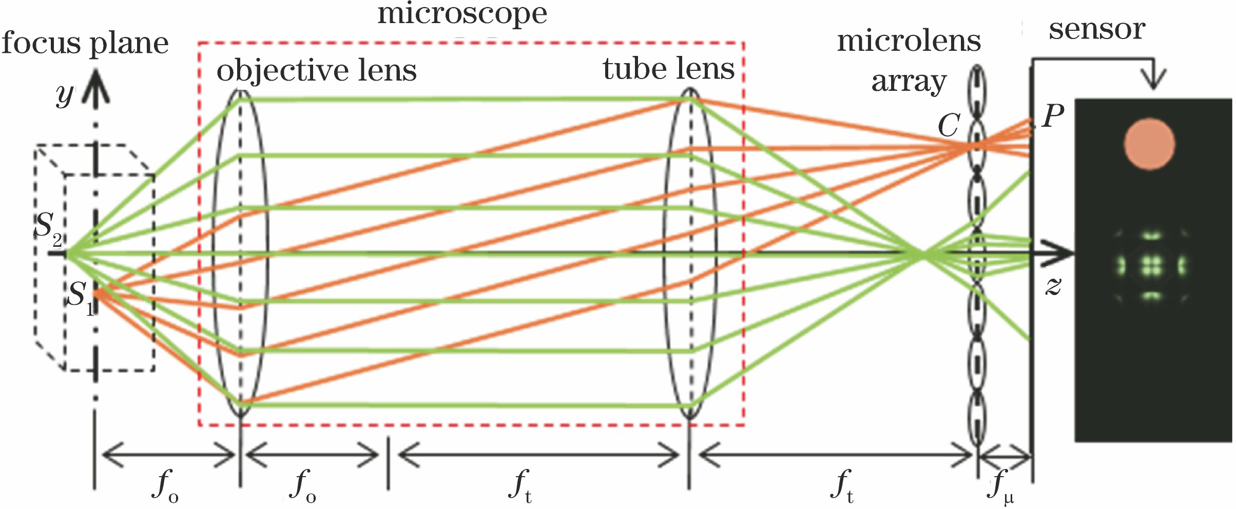
    Fig. 1. Schematic of the light field microscopic imaging (fo, ft and fμ are the focal length of the objective lens, the tube lens and the microlens, respectively)
    Schematic of the light field Micro-PIV system (Ll is the flange distance of C lens mount)
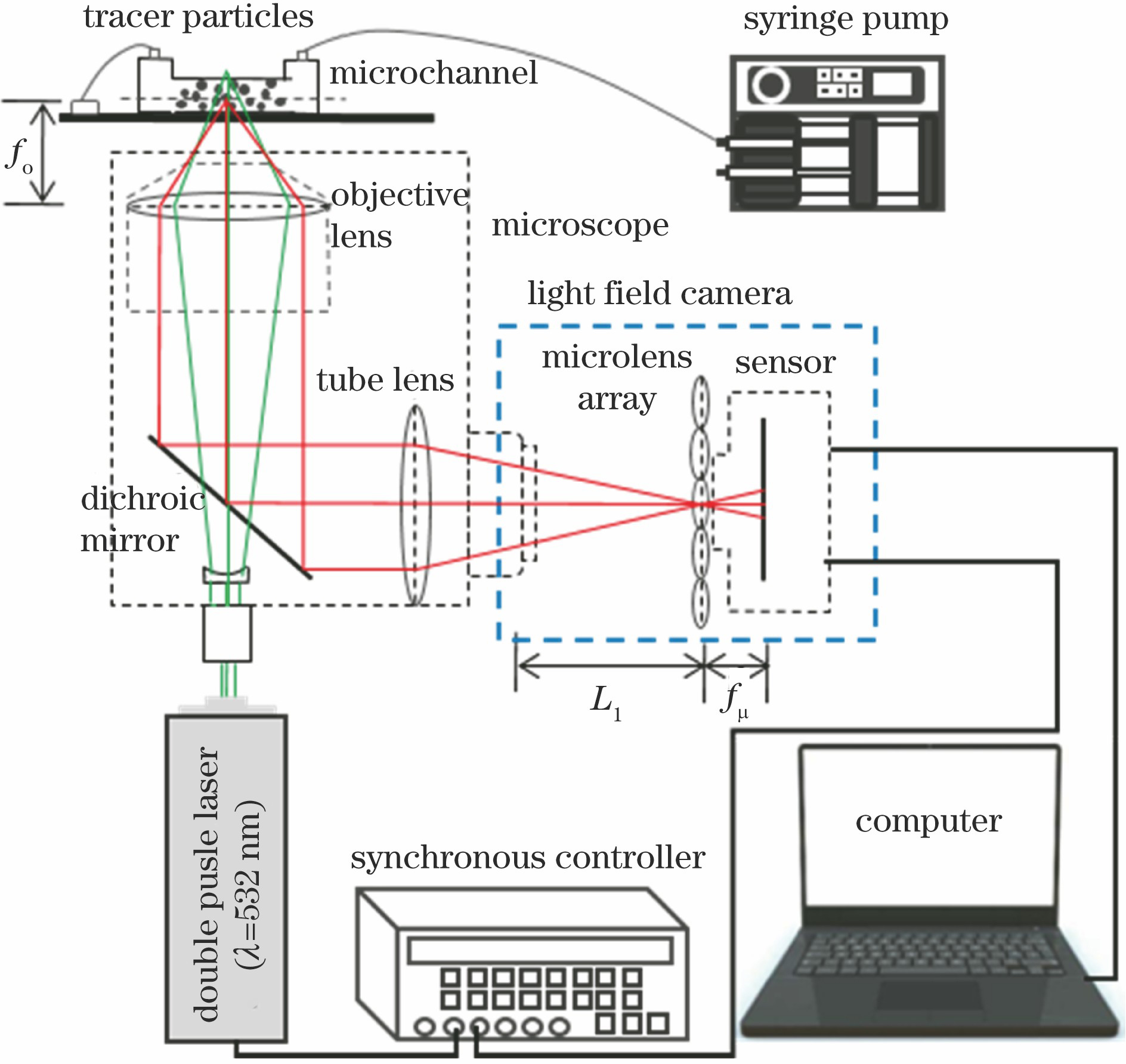
    Fig. 2. Schematic of the light field Micro-PIV system (Ll is the flange distance of C lens mount)
    Schematic of the light field microscopic imaging and the deconvolution reconstruction for micro-scale flow
    Fig. 3. Schematic of the light field microscopic imaging and the deconvolution reconstruction for micro-scale flow
    Imaging process of a point light source in light field microscopic imaging system
    Fig. 4. Imaging process of a point light source in light field microscopic imaging system
    PSFs of the light field microscopic imaging system obtained by calculation at different depths
    Fig. 5. PSFs of the light field microscopic imaging system obtained by calculation at different depths
    Photography of the experimental system
    Fig. 6. Photography of the experimental system
    Assembled cage light field camera system. (a) Schematic; (b) photography
    Fig. 7. Assembled cage light field camera system. (a) Schematic; (b) photography
    PSFs of the light field microscopic imaging system obtained by experiments at different depths
    Fig. 8. PSFs of the light field microscopic imaging system obtained by experiments at different depths
    VSSIM evaluation of PSFs calculated based on wave optics theory and obtained by experiment
    Fig. 9. VSSIM evaluation of PSFs calculated based on wave optics theory and obtained by experiment
    Reconstructed particle at z=40 μm. (a) Reconstructed tracer particle light intensity distribution; (b) front view; (c) side view
    Fig. 10. Reconstructed particle at z=40 μm. (a) Reconstructed tracer particle light intensity distribution; (b) front view; (c) side view
    Variation of the length of elongation with the defocusing distance (Rx and Rz are the results of theoretical calculation, and Rxe and Rze are the results of experiments)
    Fig. 11. Variation of the length of elongation with the defocusing distance (Rx and Rz are the results of theoretical calculation, and Rxe and Rze are the results of experiments)
    Variation of the reconstructed position error with the defocusing distance
    Fig. 12. Variation of the reconstructed position error with the defocusing distance
    Light field image of the tracer particles and reconstruction by simulation at particle concentration of 2.75×107 cm-3. (a) Light field image of tracer particles; (b) reconstructed tracer particles
    Fig. 13. Light field image of the tracer particles and reconstruction by simulation at particle concentration of 2.75×107 cm-3. (a) Light field image of tracer particles; (b) reconstructed tracer particles
    Reconstructed position errors of tracer particles at x and y directions
    Fig. 14. Reconstructed position errors of tracer particles at x and y directions
    Reconstructed position errors of tracer particles at z direction
    Fig. 15. Reconstructed position errors of tracer particles at z direction
    Light field images and reconstructed tracer particles by experiments. (a)(c) Light field images obtained at particle concentration of 2.75×106 cm-3 and 2.75×107 cm-3, respectively; (b)(d) reconstructed tracer particles at particle concentration of 2.75×106 cm-3 and 2.75×107 cm-3, respectively
    Fig. 16. Light field images and reconstructed tracer particles by experiments. (a)(c) Light field images obtained at particle concentration of 2.75×106 cm-3 and 2.75×107 cm-3, respectively; (b)(d) reconstructed tracer particles at particle concentration of 2.75×106 cm-3 and 2.75×107 cm-3, respectively
    EquipmentSymbolParameterValue
    MicroscopeMObjective lens magnification10
    NANumerical aperture of objective lens0.3
    foFocal length of objective lens /mm20
    ftFocal length of tube lens /mm200
    Cameranpx×npyResolution2352×1768
    PpPixel pitch /μm5.5
    Microlens arrayDMicrolens pitch /μm136
    fμFocal length of microlens /μm2260
    Table 1. Specific parameters of the light field microscopic imaging system
    Xianglei Song, Shu Li, Mengtao Gu, Biao Zhang, Chuanlong Xu. Three-Dimensional Reconstruction of Micro-Scale Flow Field Based on Light Field Microscopic Imaging[J]. Acta Optica Sinica, 2019, 39(10): 1011002
    Download Citation