• Matter and Radiation at Extremes
  • Vol. 5, Issue 1, 018403 (2020)
N. Hirao1、a), S. I. Kawaguchi1, K. Hirose2、3, K. Shimizu4, E. Ohtani5, and Y. Ohishi1
Author Affiliations
  • 1Japan Synchrotron Radiation Research Institute, Sayo, Hyogo 679-5198, Japan
  • 2Department of Earth and Planetary Science, The University of Tokyo, Tokyo 113-0033, Japan
  • 3Earth-Life Science Institute, Tokyo Institute of Technology, Tokyo 152-8550, Japan
  • 4Center of Science and Technology Under Extremes Conditions, Graduate School of Engineering Science, Osaka University, Osaka 560-8531, Japan
  • 5Department of Earth Science, Graduate School of Science, Tohoku University, Sendai 980-8578, Japan
  • show less
    DOI: 10.1063/1.5126038 Cite this Article
    N. Hirao, S. I. Kawaguchi, K. Hirose, K. Shimizu, E. Ohtani, Y. Ohishi. New developments in high-pressure X-ray diffraction beamline for diamond anvil cell at SPring-8[J]. Matter and Radiation at Extremes, 2020, 5(1): 018403 Copy Citation Text show less
    Energy spectra of the photon flux at a distance of 29 m from the X-ray source in a 0.5 × 0.5 mm2 slit aperture corresponding to the new in-vacuum variable-gap undulator installed at the BL10XU beamline. The spectra were calculated using SPECTRA software.42
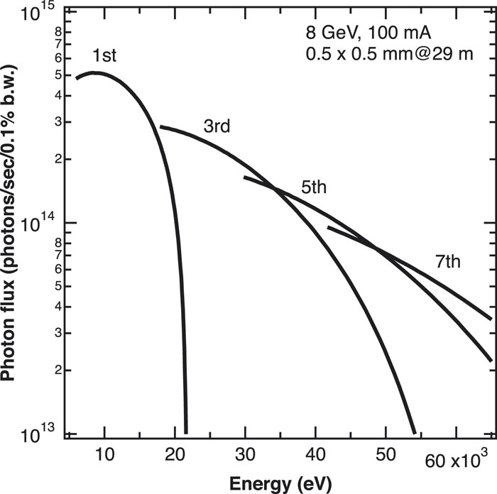
    Fig. 1. Energy spectra of the photon flux at a distance of 29 m from the X-ray source in a 0.5 × 0.5 mm2 slit aperture corresponding to the new in-vacuum variable-gap undulator installed at the BL10XU beamline. The spectra were calculated using SPECTRA software.42
    (a) X-ray focusing device system installed in OH at a distance of 42 m from the X-ray source. (b) Focusing device unit of the GC and Al CRLs. The unit consists of six lens assemblies housing the individual GC and Al CRLs, which contain (8, 16, 32, 64, 64, 64) and (4, 8, 16, 32, 56, 64) lens elements, respectively. The focused X-ray energy and the focal length can be varied by changing the combinations of the lens assembly. The SU8 CRL for submicrometer focusing has a fixed focal length of 7200 mm (see mode III in Fig. 3).
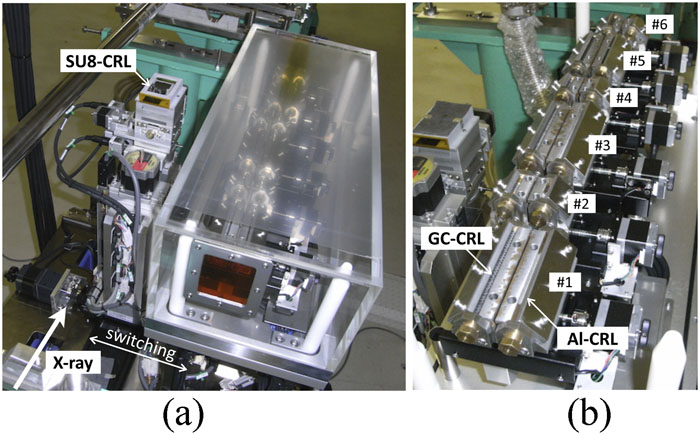
    Fig. 2. (a) X-ray focusing device system installed in OH at a distance of 42 m from the X-ray source. (b) Focusing device unit of the GC and Al CRLs. The unit consists of six lens assemblies housing the individual GC and Al CRLs, which contain (8, 16, 32, 64, 64, 64) and (4, 8, 16, 32, 56, 64) lens elements, respectively. The focused X-ray energy and the focal length can be varied by changing the combinations of the lens assembly. The SU8 CRL for submicrometer focusing has a fixed focal length of 7200 mm (see mode III in Fig. 3).
    Optical setup for X-ray focusing at 30 keV with compound refractive lens (CRL) devices at the BL10XU beamline. Mode I: single focusing setup using a collimation lens (CRL1 or CRL2) in the OH and CRL4 downstream focusing. Modes II and III: two-stage refractive focusing setup for generating 2–3 µm and 1 µm X-ray beams. CRL1, GC CRL; CRL2, Al CRL; CRL3–6, SU8 CRL; VS, a pinhole of diameter 10 µm as a virtual source; SL, incident cross slit; PH, clean-up pinhole.
    Fig. 3. Optical setup for X-ray focusing at 30 keV with compound refractive lens (CRL) devices at the BL10XU beamline. Mode I: single focusing setup using a collimation lens (CRL1 or CRL2) in the OH and CRL4 downstream focusing. Modes II and III: two-stage refractive focusing setup for generating 2–3 µm and 1 µm X-ray beams. CRL1, GC CRL; CRL2, Al CRL; CRL3–6, SU8 CRL; VS, a pinhole of diameter 10 µm as a virtual source; SL, incident cross slit; PH, clean-up pinhole.
    Intensity profiles of the focused beam measured by knife-edge scanning at 30 keV at the EH2 sample position in focusing mode III: (a) horizontal focusing; (b) vertical focusing. Open and solid circles represent the raw data and numerical differentiation of the raw profile, respectively. A Gaussian fit (thick lines) of the derivative yielded a spot size of 1.0 and 1.1 µm FWHM along the horizontal and vertical directions, respectively.
    Fig. 4. Intensity profiles of the focused beam measured by knife-edge scanning at 30 keV at the EH2 sample position in focusing mode III: (a) horizontal focusing; (b) vertical focusing. Open and solid circles represent the raw data and numerical differentiation of the raw profile, respectively. A Gaussian fit (thick lines) of the derivative yielded a spot size of 1.0 and 1.1 µm FWHM along the horizontal and vertical directions, respectively.
    (a) Microphotograph of iron in a DAC during laser heating at 5 GPa and 1500 K. (b) High-pressure scanning XRD patterns across the sample from the center to the top in 4 µm steps. In the central region of the heating spot with 20 µm diameter, the high-temperature face-centered cubic (fcc) phase of iron was observed, and the low-temperature body-centered cubic (bcc) phase appeared in the low-temperature part, which confirmed the scanning of the focused X-rays. N, NaCl; Re, rhenium gasket; r, ruby.
    Fig. 5. (a) Microphotograph of iron in a DAC during laser heating at 5 GPa and 1500 K. (b) High-pressure scanning XRD patterns across the sample from the center to the top in 4 µm steps. In the central region of the heating spot with 20 µm diameter, the high-temperature face-centered cubic (fcc) phase of iron was observed, and the low-temperature body-centered cubic (bcc) phase appeared in the low-temperature part, which confirmed the scanning of the focused X-rays. N, NaCl; Re, rhenium gasket; r, ruby.
    (a) High-pressure and low-temperature facility in the EH1. (b) In situ laser-heating facility with the DAC in the EH2 at the BL10XU beamline. (c) and (d) are schematic views of the separated X-ray diffractometers in EH1 and EH2, respectively. (1) incident cross slit; (2) gas ion chamber detector for monitoring incident beam intensity; (3) X-ray shutter and X-ray direct beam attenuator for IP detector; (4) SU8 CRL for X-ray focusing; (5) clean-up pinhole; (6) DAC; (7) IP detector; (8) photodiode for monitoring intensity of X-rays through DACs; (9) flat-panel detector (10) Raman probe.
    Fig. 6. (a) High-pressure and low-temperature facility in the EH1. (b) In situ laser-heating facility with the DAC in the EH2 at the BL10XU beamline. (c) and (d) are schematic views of the separated X-ray diffractometers in EH1 and EH2, respectively. (1) incident cross slit; (2) gas ion chamber detector for monitoring incident beam intensity; (3) X-ray shutter and X-ray direct beam attenuator for IP detector; (4) SU8 CRL for X-ray focusing; (5) clean-up pinhole; (6) DAC; (7) IP detector; (8) photodiode for monitoring intensity of X-rays through DACs; (9) flat-panel detector (10) Raman probe.
    (a) Overall view of cryostat system combined with the XRD and Raman scattering systems in EH1 at the BL10XU beamline. The green and white lines indicate the optical path of the Raman scattering measurement and the X-ray beam path, respectively. A 4K-GM cryostat with a DAC mounted on the goniometer stage is located on the heavy-duty multiaxial translation stage. (b) Cryostat DAC holder connected via a flexible bundle of copper wires to the cold stage. (c) Schematic of the low-vibration cryostat with a DAC. The DAC holder is rigidly fixed to the cryostat shield via a stainless-steel rod.
    Fig. 7. (a) Overall view of cryostat system combined with the XRD and Raman scattering systems in EH1 at the BL10XU beamline. The green and white lines indicate the optical path of the Raman scattering measurement and the X-ray beam path, respectively. A 4K-GM cryostat with a DAC mounted on the goniometer stage is located on the heavy-duty multiaxial translation stage. (b) Cryostat DAC holder connected via a flexible bundle of copper wires to the cold stage. (c) Schematic of the low-vibration cryostat with a DAC. The DAC holder is rigidly fixed to the cryostat shield via a stainless-steel rod.
    (a) Energy-domain synchrotron radiation 57Fe-Mössbauer spectroscopy system in EH1 at the BL10XU beamline. (b) Schematic of the optical system used for 57Fe-Mössbauer spectroscopy combined with synchrotron XRD. HRM, high-energy resolution monochromator consisting of nested-type channel-cut Si(511) and Si(975) crystals; NMC, nuclear monochromator crystal of 57FeBO3 near the Néel temperature and in an external magnetic field.
    Fig. 8. (a) Energy-domain synchrotron radiation 57Fe-Mössbauer spectroscopy system in EH1 at the BL10XU beamline. (b) Schematic of the optical system used for 57Fe-Mössbauer spectroscopy combined with synchrotron XRD. HRM, high-energy resolution monochromator consisting of nested-type channel-cut Si(511) and Si(975) crystals; NMC, nuclear monochromator crystal of 57FeBO3 near the Néel temperature and in an external magnetic field.
    Experimental hutch 1Experimental hutch 2
    SourceIn-vacuum undulator
    MonochromatorLiquid-nitrogen-cooled Si(111) and Si(220) double crystal
    Energy range (keV)6–61.7
    Focused beam size at 30 keV (FWHM μm2)∼10 (H)1.0 (H)3 (H)10 (H)
    ∼10 (V)1.1 (V)2 (V)7 (V)
    Flux at sample position at 30 keV (photon/s)7 × 10114 × 1091 × 10106 × 1010
    Area detectorImage plate detector, flat-panel detector
    Technique and equipment4K-GM cryostatDouble-sided laser heating
    Online Raman spectrometerOnline Raman spectrometer
    57Fe-Mössbauer spectrometerMembrane pressure control
    Membrane pressure control(4K-GM cryostat)
    Table 1. Major features of the BL10XU beamline.
    N. Hirao, S. I. Kawaguchi, K. Hirose, K. Shimizu, E. Ohtani, Y. Ohishi. New developments in high-pressure X-ray diffraction beamline for diamond anvil cell at SPring-8[J]. Matter and Radiation at Extremes, 2020, 5(1): 018403
    Download Citation