N. Hirao1,a), S. I. Kawaguchi1, K. Hirose2,3, K. Shimizu4..., E. Ohtani5 and Y. Ohishi1|Show fewer author(s)
Abstract
An overview of the recently renovated high-pressure X-ray diffraction (XRD) BL10XU beamline for the diamond anvil cell at SPring-8 is presented. The renovation includes the replacement of the X-ray source and monochromator, enhanced focusing systems for high-energy XRD, and recent progress in the sample environment control techniques that are available for high-pressure studies. Other simultaneous measurement techniques for combination with XRD, such as Raman scattering spectroscopy and M?ssbauer spectroscopy, have been developed to obtain complementary information under extreme conditions. These advanced techniques are expected to make significant contributions to in-depth understanding of various and complicated high-pressure phenomena. The experience gained with the BL10XU beamline could help promote high-pressure research in future synchrotron radiation facilities.I. INTRODUCTION
High-pressure science stands to benefit significantly from brilliant light sources operating in the high-energy X-ray region, such as third-generation large-scale synchrotron radiation facilities. X-ray diffraction (XRD) is a fundamental technique to determine crystal structures under high-pressure conditions. Hence, undulator-based high-pressure XRD beamlines have been constructed at the European Synchrotron Radiation Facility (ESRF) in Grenoble, France,1 the Advanced Photon Source (APS) at Argonne National Laboratory, USA,2,3 SPring-8 in Hyogo, Japan,4 and PETRA III at DESY in Hamburg, Germany.5
The BL10XU undulator beamline at SPring-8 is dedicated to angular dispersive XRD measurements using a highly brilliant X-ray beam at high pressure in a diamond anvil cell (DAC). Since its first operation in 1997, the main components of this beamline have been upgraded to meet the increasing demand for high-pressure XRD, for example, the X-ray source and monochromator have been replaced, there have been developments in the X-ray focusing technique, and an X-ray diffractometer has been introduced.4 High-angular-resolution XRD allows Rietveld crystal structure refinement and electron density distribution analysis by the maximum entropy method under high pressure. Additionally, to expand the accessible pressure–temperature range, various sample environment control techniques suitable for synchrotron high-pressure XRD experiments, such as laser heating and cryogenic cooling, have been optimized for studying phase relations and the P–V–T equation of state.
Consequently, the XRD experiments at BL10XU have produced many scientific breakthroughs and novel discoveries that have taken high-pressure research to a new level. Major scientific results include the discovery of MgSiO3 post-perovskite phase transitions in the lowermost part of the Earth’s mantle,6 the structural determination of O8 clusters in the ε phase of solid oxygen,7 and XRD experiments in the pressure–temperature range of the Earth’s inner core.8
Recent progress in high-pressure research has shown that pressure-induced phenomena involving crystal structures, physical properties, and chemical reactions are more complicated than previously thought. Therefore, for a comprehensive understanding of the effects of compression on materials, further high-pressure investigations are required in a number of areas, including crystal structure, molecular/lattice vibrations, and properties related to electronic structure, such as electronic and thermal conductivities, magnetic properties, electron valence states, and local atomic environments.
It is difficult to reproduce exactly the same conditions of pressure and temperature, in particular at multi-megabar pressure, between beamline and laboratory high-pressure experiments. Simultaneous or combined measurement techniques can solve this problem, as well as enhancing the throughput of measurements by means of efficient use of limited beamtime. At BL10XU, simultaneous measurement techniques with XRD have been introduced, such as Raman scattering, electrical conductivity measurement, and Mössbauer spectroscopy.
In this paper, we present recent developments in high-pressure synchrotron radiation techniques at the SPring-8 BL10XU beamline. We describe (1) the X-ray source and monochromator, (2) latest developments in X-ray focusing for high-pressure XRD, (3) a new diffractometer, (4) sample environments, and (5) simultaneous measurement techniques combined with XRD.
II. OUTLINE OF THE BEAMLINE
A. General description of the beamline
The BL10XU beamline has an optical hutch (hereinafter referred to as OH), and two experimental hutches in tandem.4 The first experimental hutch (EH1) is fully optimized for high-pressure and low-temperature XRD experiments using a cryostat. The second experimental hutch (EH2) is dedicated to high-pressure and high-temperature experiments using a laser or resistively heated DACs. Table I summarizes the main characteristics of the experimental hutches.
| Experimental hutch 1 | Experimental hutch 2 |
|---|
| Source | In-vacuum undulator |
| Monochromator | Liquid-nitrogen-cooled Si(111) and Si(220) double crystal |
| Energy range (keV) | 6–61.7 |
| Focused beam size at 30 keV (FWHM μm2) | ∼10 (H) | 1.0 (H) | 3 (H) | 10 (H) |
| ∼10 (V) | 1.1 (V) | 2 (V) | 7 (V) |
| Flux at sample position at 30 keV (photon/s) | 7 × 10¹¹ | 4 × 10⁹ | 1 × 10¹⁰ | 6 × 10¹⁰ |
| Area detector | Image plate detector, flat-panel detector |
| Technique and equipment | 4K-GM cryostat | Double-sided laser heating |
| Online Raman spectrometer | Online Raman spectrometer |
| 57Fe-Mössbauer spectrometer | Membrane pressure control |
| Membrane pressure control | (4K-GM cryostat) |
Table 1. Major features of the BL10XU beamline.
B. X-ray source and monochromator
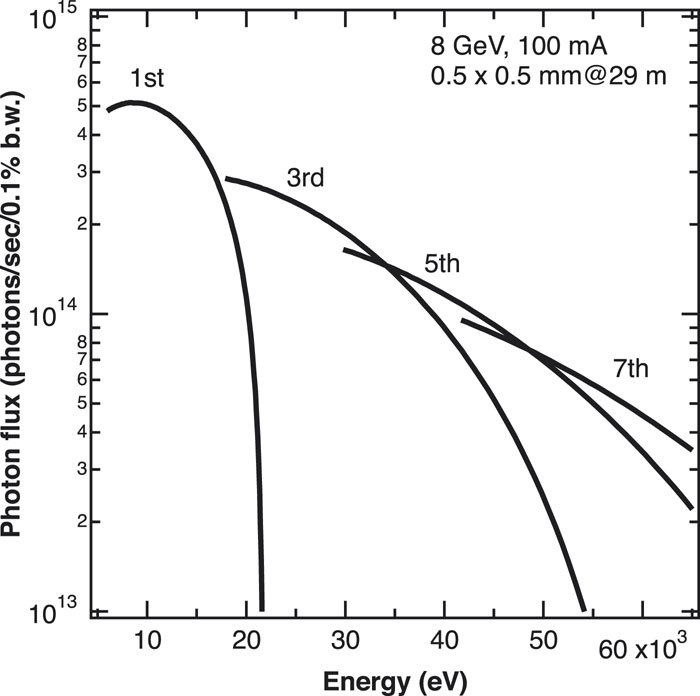
A newly developed in-vacuum undulator (IVU-II) was installed as an insertion device to the X-ray source at BL10XU in April 2019. This undulator replaced the previous one4 to expand the lowest available X-ray energy down to 6 keV. A notable feature of IVU-II is the magnetic attractive force cancellation system based on multipole monolithic magnets.9 This system allows for a more compact and lightweight design than is possible with the conventional undulators of SPring-8. The total length of IVU-II is 3.6 m in the longitudinal direction, compared with 4.5 m for the conventional design. The new undulator installed at BL10XU has a magnetic array with 128 periods, each of length 28 mm. A maximum field of 0.87 T can be obtained at a gap of 8 mm. The fundamental, third, fifth, and seventh harmonics of the radiation cover the photon energy ranges of 5.9–21, 18–65, 30–108, and 42–147 keV, respectively (Fig. 1). It is also planned to install the IV-II at other undulator beamlines in SPring-8 II (the upgrade project of SPring-8).10

Figure 1.Energy spectra of the photon flux at a distance of 29 m from the X-ray source in a 0.5 × 0.5 mm2 slit aperture corresponding to the new in-vacuum variable-gap undulator installed at the BL10XU beamline. The spectra were calculated using SPECTRA software.42
A SPring-8 standard double-crystal monochromator (DCM)11 is located in the OH at a distance of 37.6 m from the X-ray source. This liquid-nitrogen-cooled monochromator12,13 consists of two pairs of Si crystals with (111) and (220) reflection planes and can deliver a monochromatic beam from 6.0 to 61.7 keV for high-pressure X-ray experiments. The Si crystals with different reflection planes are switchable using a linear translation stage in the vacuum chamber. The Si(111) reflection is used in the energy range of 6.0 keV (λ = 2.00 Å) to 37.8 keV (λ = 0.33 Å), and the Si(220) reflection is used from 37.8 to 61.7 keV (λ = 0.20 Å). The current monochromator replaced a water-cooled diamond (111) monochromator4 in 2013, bringing about substantial improvements, including an extension of the available X-ray energy ranges and an increase in the X-ray beam intensity at the sample position by a factor of 10.
C. X-ray focusing
High-energy focused X-ray probes are essential for high-pressure XRD with DACs involving minute samples. At BL10XU, a compound refractive lens (CRL) has been used to focus the X-ray beam.4,14 Compared with other X-ray focusing optics (e.g., Kirkpatrick–Baez mirrors and Fresnel zone plates), CRL-based focusing optics offer advantages such as an on-axis geometry (in-line optics), suitability for high-energy X-ray ranges, tunability of the focal distance, simplicity of alignment and operation, and easy installation.
The X-ray focusing system based on CRLs was developed and installed in the OH at a distance of 42.0 m from the X-ray source, in order to accept a high-energy X-ray beam over 40 keV and generate a submicrometer focused beam at 30 keV. The system includes three kinds of CRL groups (Fig. 2), and each lens is made from glassy carbon (GC)4 for focusing up to 40 keV, aluminum (Al) for 40–61.7 keV, and SU8 polymer15 for submicrometer focusing. The GC and Al CRLs are also used to prefocus or collimate the X-ray beams from the monochromator.
Figure 2.(a) X-ray focusing device system installed in OH at a distance of 42 m from the X-ray source. (b) Focusing device unit of the GC and Al CRLs. The unit consists of six lens assemblies housing the individual GC and Al CRLs, which contain (8, 16, 32, 64, 64, 64) and (4, 8, 16, 32, 56, 64) lens elements, respectively. The focused X-ray energy and the focal length can be varied by changing the combinations of the lens assembly. The SU8 CRL for submicrometer focusing has a fixed focal length of 7200 mm (see mode III in Fig. 3).
Figure 3 shows the focusing layouts using X-ray CRLs. Three focusing modes can be utilized according to the purpose of the high-pressure XRD experiments. The CRL focusing system at BL10XU is basically optimized for a monochromatic beam of 30 keV. This X-ray energy is selected on the basis of factors for general high-pressure XRD experiments, such as accessible reciprocal space, DAC opening angle, X-ray intensity, detector efficiency, spatial resolution (pixel size), and angular resolution of the X-ray beam.
Figure 3.Optical setup for X-ray focusing at 30 keV with compound refractive lens (CRL) devices at the BL10XU beamline. Mode I: single focusing setup using a collimation lens (CRL1 or CRL2) in the OH and CRL4 downstream focusing. Modes II and III: two-stage refractive focusing setup for generating 2–3 µm and 1 µm X-ray beams. CRL1, GC CRL; CRL2, Al CRL; CRL3–6, SU8 CRL; VS, a pinhole of diameter 10 µm as a virtual source; SL, incident cross slit; PH, clean-up pinhole.
In the first focusing mode (hereinafter referred to as mode I), a high-flux X-ray beam can be used for general high-pressure XRD experiments. The beam size, which is defined as the full width at half maximum (FWHM) of the intensity profile, is 10 (horizontal) × 7 (vertical) μm2 at the sample position in EH2. The flux is 6 × 10¹⁰ photons/s when an incident cross slit size of 20 × 20 µm2 and a 10 µm cleanup pinhole are used. When the aperture size is set to 100 × 100 µm2 using the cross slit, the X-ray beam flux can be increased to 7 × 10¹¹ photons/s, with a slight broadening of the focusing size. A focused X-ray beam with almost the same size and flux is also available in EH1.
A two-stage CRL focusing system comprising two CRLs and a pinhole achieves a smaller beam spot at an X-ray energy of 30 keV. The X-ray beam delivered from the DCM is focused at the pinhole position by the first SU8 CRL, and the beam passing through the pinhole is then focused at the sample position in EH2 by the second SU8 CRL (Fig. 3). In mode II, the beam size can be focused down to 3 (H) × 2 (V) μm2, with a resulting flux of 1 × 10¹⁰ photons/s. The high-intensity X-ray beam with a size of 2–3 µm is very useful for laser-heating XRD experiments, as described in Sec. III B. Mode III (a similar focusing setup to mode II, but with a different demagnification ratio) successfully generates an X-ray beam with a spot size of 1.0 (H) × 1.1 (V) μm2 and s flux of 4 × 10⁹ photons/s (Fig. 4). The high-spatial-resolution X-ray beam enables diffraction experiments of micrometer-sized samples at multimegabar pressures, such as XRD data collection at more than 400 GPa16 and high-pressure studies using a double stage DAC.17,18
Figure 4.Intensity profiles of the focused beam measured by knife-edge scanning at 30 keV at the EH2 sample position in focusing mode III: (a) horizontal focusing; (b) vertical focusing. Open and solid circles represent the raw data and numerical differentiation of the raw profile, respectively. A Gaussian fit (thick lines) of the derivative yielded a spot size of 1.0 and 1.1 µm FWHM along the horizontal and vertical directions, respectively.
Recently, we have developed a new scanning XRD method as an application of the two-stage CRL focusing technique. A microfocused X-ray beam can be scanned by moving the focusing optics of SU8 CRL (CRL4 in Fig. 3), which are entirely different from the conventional methods that require scanning of the sample position. As the new method allows the sample to be fixed, it is beneficial for laser-heated and cryogenically cooled samples. We have succeeded in scanning the 2–3 μm-focused beam (mode II) in the 40 × 40 µm2 range and have performed laser-heated XRD experiments as a demonstration of this new method (Fig. 5).
Figure 5.(a) Microphotograph of iron in a DAC during laser heating at 5 GPa and 1500 K. (b) High-pressure scanning XRD patterns across the sample from the center to the top in 4 µm steps. In the central region of the heating spot with 20 µm diameter, the high-temperature face-centered cubic (fcc) phase of iron was observed, and the low-temperature body-centered cubic (bcc) phase appeared in the low-temperature part, which confirmed the scanning of the focused X-rays. N, NaCl; Re, rhenium gasket; r, ruby.
D. X-ray diffractometer
We installed a separated X-ray diffractometer consisting of rigid stages that can independently mount three components: incident X-ray optics, a heavy-duty goniometer for DACs, and X-ray detectors (Fig. 6). In this separated system, the vibration and the stage distortion from the cryostat and detectors can be cut off. The separated X-ray diffractometer in EH1 was built in 2009, and a similar diffractometer was installed in EH2 in 2014. The incident X-ray optics devices, including the CRL, are mounted on a motorized linear stage that can be moved with submicrometer accuracy in the horizontal and vertical directions. The high-precision heavy-duty DAC goniometer stage is equipped for versatile high-pressure XRD applications, with a cryostat, a vacuum chamber for resistive heating, and precise-positioning adjustment stages. The DAC goniometer stage consists of a three-axis linear translation stage and a rotation stage.
Figure 6.(a) High-pressure and low-temperature facility in the EH1. (b) In situ laser-heating facility with the DAC in the EH2 at the BL10XU beamline. (c) and (d) are schematic views of the separated X-ray diffractometers in EH1 and EH2, respectively. (1) incident cross slit; (2) gas ion chamber detector for monitoring incident beam intensity; (3) X-ray shutter and X-ray direct beam attenuator for IP detector; (4) SU8 CRL for X-ray focusing; (5) clean-up pinhole; (6) DAC; (7) IP detector; (8) photodiode for monitoring intensity of X-rays through DACs; (9) flat-panel detector (10) Raman probe.
XRD can be recorded using two types of area detectors (Fig. 6). One is an image plate detector (IP: Rigaku R-AXIS IV++, 300 × 300 mm2, and 0.10 mm pixel size). This large-area detector can access a wide range of momentum transfers in reciprocal space and has a wide dynamic range (20 bit) and low background. The IP detector is utilized mainly for precise crystal structure analysis that requires accurate determination of the XRD peak intensities with high angular resolution over a wide angular region. Another detector is a flat-panel detector (FPD: Perkin Elmer XRD0822, 1024 × 1024 pixels, 200 µm/pixel, CsI deposited type, with 16-bit dynamic range), which has been installed in EH1 and EH2 since 2015 and 2014, respectively. The FPD has a maximum readout speed of 25 frames/s and is a suitable device for conducting fast time-resolved XRD experiments and real-time monitoring under extreme conditions, including high pressure and high temperature.
Two detectors are mounted on the motorized positioning stage in a horizontal direction perpendicular to the X-ray beam and can be switched quickly depending on the experimental requirements. The observed area in reciprocal lattice space is optimized by moving each detector laterally around the X-ray beam axis using the motorized linear stage and also by moving along the X-ray beam axis. The sample-to-detector distance (camera length) for the IP can be varied from 220 to 450 mm using another motorized linear stage. The FPD is available at the following fixed distances: 250–450 mm in EH1 and 200, 250, 300 mm in EH2. XRD measurements with the use of the IP detector have the highest angular resolution of 0.013° at a camera length of 450 mm, and the maximum detectable diffraction angle is extended to at least 45° at a camera length of 220 mm and laterally off-centered position.
III. SAMPLE ENVIRONMENTS
A. Cryogenic cooling
A low-vibration helium-flow, closed-cycle 4K Gifford–McMahon (GM) (CRT-DAC-U404, ULVAC) cryostat has been installed in EH1. A helium-gas-driven membrane-type DAC can be inserted in the cryostat. Sample pressures in the DAC can be controlled remotely and continuously by gas pressure in the membrane at low temperature, which allows in situ high-pressure and low-temperature XRD experiments. High-pressure XRD measurements using DACs require stability of the sample position, and this is critical in experiments using the focused X-ray beam for tiny samples, particularly in multimegabar high-pressure experiments.
Vibration due to piston movement in the refrigerator head presents a serious problem for samples in DACs. To reduce the vibration of the DAC in the cryostat to 5 µm or less, the DAC mount holder is supported by a stainless-steel rod fixed to the cryostat shroud and is connected to the cold head of the refrigerator by nonrigid copper wire bundles (Fig. 7). Thermal conduction between the cold head and the DAC holder is sufficiently effective, and the lowest DAC temperature of 7 K can be reached within 2 h. The temperature of the sample in the cryostat is controlled by the DC electric power of the wire heater through a proportional–integral–derivative (PID) control loop.
Figure 7.(a) Overall view of cryostat system combined with the XRD and Raman scattering systems in EH1 at the BL10XU beamline. The green and white lines indicate the optical path of the Raman scattering measurement and the X-ray beam path, respectively. A 4K-GM cryostat with a DAC mounted on the goniometer stage is located on the heavy-duty multiaxial translation stage. (b) Cryostat DAC holder connected via a flexible bundle of copper wires to the cold stage. (c) Schematic of the low-vibration cryostat with a DAC. The DAC holder is rigidly fixed to the cryostat shield via a stainless-steel rod.
This cryostat is installed in a central through-hole of the goniometer (Huber 430), and is held in a horizontal orientation for XRD data collection in the vertical oscillation mode (Fig. 7). The cryostat has two windows to accommodate XRD and optical measurements in forward and backward scattering geometries, respectively. One is a Mylar window that has a large opening angle of 60° for powder XRD using the oscillation technique or for single-crystal XRD. The other window is made from quartz glass and is used for sample observation and Raman spectroscopy measurements (see Sec. IV A).
Numerous XRD experiments under high-pressure and low-temperature conditions have been carried out using the low-vibration cryostat.19,20 The same cryostat has recently been installed in EH2 for high-pressure and low-temperature XRD measurements using the high-spatial-resolution X-ray focused beam.
B. Laser heating
A double-sided laser heating system for DACs has been installed to perform high-pressure and high-temperature XRD in EH2,4,21 and it has been utilized to study the deep Earth and planets, as well as synthesis of novel materials such as hydrides.8,22–24
The present laser heating system is composed of two high-power lasers together with laser delivery and temperature measurement optics. The water-cooled 100 W continuous-wave (CW) fiber laser (SPI Lasers Limited, λ = 1070 nm) is operated in the Gaussian mode (TEM00). The laser power can be controlled independently both upstream and downstream. The two laser beams are converted to flat-top profiles using beam-shaping optics and then delivered to a sample in a DAC from both sides using GC mirrors coated with silver.4 The GC mirrors allow high-energy incident the X-ray beam and XRD signal to pass through.
A defocusing technique is employed to change the laser spot size in a short time, depending on the required experimental conditions. The heating area is ∼10–40 µm in diameter, which is much larger than the focused X-ray beam with a 2–3 µm diameter (mode II in Fig. 3). A combination of the defocusing and double-sided laser heating techniques (which can reduce the temperature gradient in the axial direction of a sample in a DAC) allows quantitative XRD measurements to be performed under high-pressure and high-temperature conditions.
The thermal radiation spectrum is collected using a spectrograph system (HRS300, Teledyne Princeton Instruments) and fitted to the Plank radiation function to measure temperatures simultaneously on both sides of the laser-heated sample. The system includes interchangeable two-area detectors: a sensitive EM-CCD camera (ProEM-HS: 512BX3, Teledyne Princeton Instruments) for fast temperature measurements and a near-infrared-sensitive CCD camera (Blaze 400-HR, Teledyne Princeton Instruments) for lower-temperature measurements.
Recently, we have introduced a few modifications to improve the system performance and reliability for laser heating: (1) a precise-motorized optics stage dedicated to the laser-heating system (Fig. 6), (2) a thick honeycomb optical breadboard, and (3) a new optomechanical unit. The optics stage for the laser-heating system is entirely independent of the X-ray diffractometer and the detection system. Moving the stage along the horizontal and vertical directions perpendicular to the X-ray beam axis allows the laser beam to be quickly adjusted to the X-ray beam position and requires little alignment of the laser optics. The previous honeycomb optical breadboard of thickness 48 mm was replaced by a high-rigidity steel honeycomb breadboard of thickness 109 mm to improve stiffness and stability. A motorized gimbal-type mirror-mount unit was developed for the laser-beam delivery. The previous mirror mount was a kinematic type and was fixed by suspending the GC mirror, but the new mount can firmly support the mirror from the bottom side. As a result, the new laser-heating system enables precise position control of the laser beam with much better stability.
IV. SIMULTANEOUS/COMBINED MEASUREMENT WITH XRD
To realize the simultaneous or combined measurement of XRD with other measurement techniques at high pressure, it is necessary to design and develop instruments that can coexist with the X-ray diffractometer, including the X-ray optics and the detection system. We have already devised new Raman scattering spectroscopy, electrical resistivity measurement, Mössbauer spectroscopy, and Brillouin scattering spectroscopy equipment. The first three of these techniques are described below. It should be noted that the Brillouin scattering spectrometer, which had been installed in EH1,4,25 was removed following successful completion of the project.26–28
A. Raman scattering spectroscopy
Raman scattering spectroscopy provides complementary information to XRD regarding crystal structure and phase transitions under high pressures via vibrational selection rules and changes in vibrational excitation energies. This technique also plays a vital role in in situ pressure determination in high-pressure and low-temperature XRD experiments using the Raman shift of the diamond anvils.29,30
An online micro-Raman scattering optics unit (hereinafter referred to as the Raman probe) that is designed to be compact and lightweight has been installed in the experimental hutch (Figs. 6 and 7). The Raman probe is fiber-coupled with an excitation laser and spectrometer placed outside the experimental hutch and consists of the following optical components: a laser clean-up filter, a dichroic mirror, an objective lens, illumination, a CCD camera for sample observation, a mechanical shutter, and focusing optics. A diode-pumped solid-state laser, operating at 532 nm with a maximum output power of 100 mW, has been installed as an excitation light source to collect the Raman spectra. The Raman signal is dispersed using a spectrometer with a focal length of 500 mm (SP2500i, Teledyne Princeton Instruments) and with three gratings (600, 1200, and 1800 grooves/mm) and is detected by a 2048 pixel CCD (PIXIS 2k, Teledyne Princeton Instruments).
The Raman probe of EH1 is placed upstream of the sample and is positioned so as not to interfere with incident X-ray optics and XRD measurements (Fig. 7). The Raman spectrum in the backward-scattering geometry can always be measured even during XRD data acquisition by using the X-ray transparent silver-coated GC mirror and a specially designed objective lens with a long working distance of 95 mm. The similar EH2 Raman probe with a Mitutoyo 20× objective lens (M Plan Apo SL20×, Mitutoyo) is mounted between the IP detector and FPD on the detector translation stage (Fig. 6).
For the first time, the isostructural transition from phase II to III of solid hydrogen was confirmed under low-temperature and high-pressure conditions using a combination of in situ Raman scattering and XRD measurements.31 The phase transition was identified by a sizable discontinuous drop in the Raman vibrational frequency. The XRD results indicate that phases II and III remain in the hcp lattice and the lattice parameter c decreases abruptly at the II–III transition. For another example, in the pressure–temperature–composition phase diagram of the N2–O2 binary system, supporting evidence for the formation of the kagome lattice with O2 was obtained from the Raman scattering results.32,33
B. Electrical resistivity measurement
High-pressure electrical resistance measurement is one of the primary and essential observation methods for physical property research. Simultaneous measurements of XRD and electrical resistivity under high-pressure and low-temperature conditions contribute to crystal structure determination at pressure-induced transitions, including metal–semiconductor and superconducting transitions, and provide critical information for understanding the mechanism. In the low-vibration cryostats at BL10XU, electrical signal lines have been installed for simultaneously measuring electrical resistivity and XRD.
In the last decade, novel high-pressure experiments have been conducted, such as determining the crystal structure of hydrogen sulfide with a high-Tc superconducting transition temperature of 200 K,34 structural analysis of the metal–semiconductor and reentrant metal transitions of lithium,35,36 and establishing the complex structure of the superconducting phase of calcium as the highest Tc element.37 Recently, the four-point probe method has also been applied to laser-heated DACs, and the electrical conductivity of deep Earth materials has been studied under extreme conditions.22,23
C. Mössbauer spectroscopy
Iron (Fe) is by far the most abundant transition-metal element in the composition of the Earth and is a crucial element in deep Earth studies. 57Fe-Mössbauer spectroscopy is a well-established probe for studying the behavior of iron in a crystal structure and its electronic and magnetic properties, since the valence or magnetic state of iron cannot be determined using XRD. Recently, an energy-domain synchrotron radiation 57Fe-Mössbauer absorption spectrometer has been developed at SPring-838 and ESRF.39 As a well-collimated undulator X-ray beam can be utilized in this method under any storage ring bunch mode operation, it is expected to be measured simultaneously with high-pressure XRD in DACs. This combination is a powerful technique to understand the complicated high-pressure behavior of deep Earth materials.
An energy-domain synchrotron 57Fe-Mössbauer spectroscopy system was designed for combinatorial studies at BL10XU and installed on the downstream side of the EH1 X-ray diffractometer (Fig. 8). The system has all the components for 57Fe-Mössbauer spectroscopy, including a nested high-resolution monochromator (HRM) with asymmetric Si(511) and symmetric Si(975) channel-cut crystals, a variable-frequency iron borate (FeBO3) single crystal unit, and an NaI scintillation detector.32 The HRM has been installed to tune the X-ray beam energy around the nuclear resonance energy of 57Fe and reduce the background signals from electronic scattering. A 95% 57Fe-enriched FeBO3 single crystal, heated to the Néel temperature and with a 160 G external magnetic field applied, can produce ultrafine monochromatic X-rays with a bandwidth of ∼15 neV using pure nuclear Bragg reflection (333) as a nuclear monochromator. This nuclear monochromator is mounted on a velocity transducer and is energy-modulated in the sinusoidal velocity mode. Consequently, the X-ray beam through a sample can be filtered by Doppler-shifted single-line 57Fe-Mössbauer radiation. The Mössbauer absorption spectrum is then measured by counting the intensity of the single-line nuclear Bragg reflection as a function of velocity.
Figure 8.(a) Energy-domain synchrotron radiation 57Fe-Mössbauer spectroscopy system in EH1 at the BL10XU beamline. (b) Schematic of the optical system used for 57Fe-Mössbauer spectroscopy combined with synchrotron XRD. HRM, high-energy resolution monochromator consisting of nested-type channel-cut Si(511) and Si(975) crystals; NMC, nuclear monochromator crystal of 57FeBO3 near the Néel temperature and in an external magnetic field.
A typical example of combined XRD and 57Fe-Mössbauer spectroscopy involves high-pressure experiments on metallic iron–silicon alloys at up to 60 GPa at room temperature.40 The spin state and electronic environment of iron have also been investigated in basaltic glass under lower-mantle conditions.41
V. SUMMARY
We have optimized the X-ray source, X-ray monochromator, and X-ray focusing device to perform quantitative high-pressure XRD measurements using the high-energy microfocused X-ray beam at the SPring-8 BL10XU beamline. Simultaneous measurement techniques, such as combinations of XRD with Raman scattering spectroscopy and 57Fe-Mössbauer spectroscopy, have been developed and installed for comprehensive studies under extreme high-pressure and high/low-temperature conditions. New techniques for combining XRD with full-field imaging and X-ray absorption spectroscopy are under development at the beamline. We also plan to install a new high-performance X-ray detector for XRD with a photon-countable, high-frame-rate, and energy threshold capability to perform structural analysis on liquid and amorphous materials and low-Z materials, as well as for observing fast and transient phenomena.
Upgrade projects implementing ultralow-emittance high-energy synchrotron radiation facilities have been launched at the third-generation high-energy synchrotron radiation facilities SPring-8, ESRF, APS, and PETRA-III. Such future light sources will dramatically increase both brightness and coherence for high-energy X-rays and will allow new nanobeam XRD and coherent-based XRD imaging techniques. These techniques will extend the pressure range and facilitate metascale structural analysis for high-pressure studies. Nevertheless, we believe that, even in future synchrotron radiation facilities, it is essential to increase the sophistication of high-pressure XRD techniques and to install state-of-the-art techniques for combinatorial studies. We will continue to actively develop the simultaneous/combined measurement of XRD with other techniques to provide greater understanding of a variety of complicated pressure-induced phenomena.
References
[1] S. Bauchau, G. Blattmann, C. Borel, J. Chavanne, W. A. Crichton, Y. Dabin, O. Hignette, P. Marion, M. Mezouar, C. Morawe, F. Thurel, F. Torrecillas, H. Witsch. Development of a new state-of-the-art beamline optimized for monochromatic single-crystal and powder X-ray diffraction under extreme conditions at the ESRF. J. Synchrotron Radiat., 12, 659(2005).
[2] P. J. Eng, V. B. Prakapenka, M. L. Rivers, G. Shen, S. R. Sutton. Facilities for high-pressure research with the diamond anvil cell at GSECARS. J. Synchrotron Radiat., 12, 642(2005).
[3] R. Boehler, R. Hrubiak, Y. Meng, E. Rod, G. Shen. New developments in laser-heated diamond anvil cell with in situ synchrotron x-ray diffraction at High Pressure Collaborative Access Team. Rev. Sci. Instrum., 86, 072201(2015).
[4] N. Hirao, K. Hirose, Y. Ohishi, N. Sata, M. Takata. Highly intense monochromatic X-ray diffraction facility for high-pressure research at SPring-8. High Pressure Res., 28, 163(2008).
[5] J. Bednarčik, Y. Bican, J. T. Delitz, A. Ehnes, H. Franz, K. Glazyrin, J. Heuer, Z. Konôpková, T. Kracht, H.-P. Liermann, E. E. McBride, W. Morgenroth, S. Petitgirard, A. Rothkirch, H. Schulte-Schrepping, I. Schwark, M. Tischer, M. Wendt. The extreme conditions beamline P02.2 and the extreme conditions science infrastructure at PETRA III. J. Synchrotron Radiat., 22, 908(2015).
[6] K. Hirose, K. Kawamura, M. Murakami, Y. Ohishi, N. Sata. Post-perovskite phase transition in MgSiO3. Science, 304, 855(2004).
[7] Y. Akahama, H. Fujihisa, Y. Gotoh, K. Honda, H. Kawamura, Y. Ohishi, M. Sakashita, O. Simomura, S. Takeya, H. Yamawaki. O8 cluster structure of the epsilon phase of solid oxygen. Phys. Rev. Lett., 97, 085503(2006).
[8] K. Hirose, Y. Ohishi, S. Tateno, Y. Tatsumi. The structure of iron in Earth’s inner core. Science, 330, 359(2010).
[9] A. Kagamihata, R. Kinjo, H. Kishimoto, H. Ohashi, T. Seike, T. Tanaka, S. Yamamoto. Lightweight-compact variable-gap undulator with force cancellation system based on multipole monolithic magnets. Rev. Sci. Instrum., 88, 073302(2017).
[10] S. Goto, T. Ishikawa, S. Matsuyama, H. Mimura, H. Ohashi, K. Tamasaku, H. Tanaka, T. Tanaka, K. Tono, M. Yabashi, K. Yamauchi. Optics for coherent X-ray applications. J. Synchrotron Radiat., 21, 976(2014).
[11] Y. Furukawa, S. Goto, T. Ishikawa, T. Mochizuki, S. K. Takeshita, K. Tamasaku, M. Yabashi, H. Yamazaki, Y. Yoneda. SPring-8 standard x-ray monochromators. Proc. SPIE, 3773, 2(1999).
[12] A. Awaji, A. Barona, T. Ishikawa, Y. Kohmura, T. Mochizuki, Y. Suzuki, K. Tamasaku, M. Yabashi, H. Yamazaki. Cryogenic cooling monochromators for the SPring-8 undualtor beamlines. Nucl. Instrum. Methods Phys. Res. A, 467-468, 647(2001).
[13] S. Goto, T. Ishikawa, H. Kishimoto, Y. Matsuzaki, T. Miura, H. Ohashi, Y. Senba, Y. Shimizu, M. Suzuki, H. Tajiri, M. Takata, T. Takeuchi, M. Tanaka, Y. Terada, M. Yamamoto, H. Yamazaki. Improvement in stability of SPring-8 X-ray monochromators with cryogenic-cooled silicon crystals. J. Phys. Conf. Ser., 425, 052001(2013).
[14] A. Q. R. Baron, M. Ishii, T. Ishikawa, Y. Ohishi, O. Shimomura. Refractive x-ray lens for high pressure experiments at SPring-8. Nucl. Instrum. Methods Phys. Res. A, 467-468, 962(2001).
[15] J. Mohr, V. Nazmov, E. Reznikova, V. Saile, A. Somogyi. Planar sets of cross X-ray refractive lenses from SU-8 polymer. Proc. SPIE, 5539, 235-243(2004).
[16] Y. Akahama, N. Hirao, Y. Ohishi, A. K. Singh. Equation of state of bcc-Mo by static volume compression to 410 GPa. J. Appl. Phys., 116, 223504(2014).
[17] T. Asakawa, N. Hirao, T. Irifune, T. Kanemura, Y. Kuroda, H. Ohfuji, Y. Ohishi, T. Sakai, Y. Suzuki, T. Yagi. High-pressure generation using double stage micro-paired diamond anvils shaped by focused ion beam. Rev. Sci. Instrum., 86, 033905(2015).
[18] N. Hirao, K. Hirose, T. Irifune, H. Kadobayashi, S. Kawaguchi-Imada, T. Kunimoto, H. Ohfuji, Y. Ohishi, T. Sakai, S. Tateno, T. Yagi. High pressure generation using double-stage diamond anvil technique: Problems and equations of state of rhenium. High Pressure Res., 38, 107(2018).
[19] S. Desgreniers, Q. Li, Y. Ma, T. Matsuoka, Y. Ohishi, J. S. Tse. High pressure–low temperature phase diagram of barium: Simplicity versus complexity. Appl. Phys. Lett., 107, 221908(2015).
[20] D. Arčon, A. Y. Ganin, Y. Iwasa, P. Jeglič, Y. Ohishi, K. Prassides, M. J. Rosseinsky, Y. Takabayashi, T. Takano, M. Takata, N. Takeshita. The disorder-free non-BCS superconductor Cs3C60 emerges from an antiferromagnetic insulator parent state. Science, 323, 1585(2009).
[21] M. Isshiki, T. Kondo, O. Shimomura, T. Watanuki, T. Yagi. Construction of laser-heated diamond anvil cell system for in situ x-ray diffraction study at SPring-8. Rev. Sci. Instrum., 72, 1289(2001).
[22] K. Hirose, Y. Ohishi, K. Ohta, S. Onoda, N. Sata, K. Shimizu, R. Sinmyo, A. Yasuhara. The electrical conductivity of post-perovskite in Earth’s D” layer. Science, 320, 89(2008).
[23] K. Hirose, Y. Kuwayama, Y. Ohishi, K. Ohta, K. Shimizu. Experimental determination of the electrical resistivity of iron at Earth’s core conditions. Nature, 534, 95(2016).
[24] G. J. Ackland, J. Binns, P. Dalladay-Simpson, E. Gregoryanz, R. Howie, M. Wang. Formation of H2-rich iodine-hydrogen compounds at high pressure. Phys. Rev. B, 97, 024111(2018).
[25] Y. Asahara, N. Hirao, K. Hirose, M. Murakami, Y. Ohishi. Development of in situ Brillouin spectroscopy at high pressure and high temperature with synchrotron radiation and infrared laser heating system: Application to the Earth’s deep interior. Phys. Earth Planet. Inter., 174, 282(2009).
[26] N. Hirao, K. Hirose, M. Murakami, Y. Ohishi. A perovskitic lower mantle inferred from high-pressure, high-temperature sound velocity data. Nature, 485, 90(2012).
[27] Y. Asahara, N. Hirao, K. Hirose, Y. Kudo, M. Murakami, Y. Ohishi, H. Ozawa. Sound velocity measurements of CaSiO3 perovskite to 133 GPa and implications for lowermost mantle seismic anomalies. Earth Planet. Sci. Lett., 349-350, 1(2012).
[28] Y. Asahara, N. Hirao, K. Hirose, M. Murakami, Y. Ohishi, H. Ozawa. Acoustic velocity measurements for stishovite across the post-stishovite phase transition under deviatoric stress: Implications for the seismic features of subducting slabs in the mid-mantle. Am. Mineral., 98, 2053(2013).
[29] Y. Akahama, H. Kawamura. High-pressure Raman spectroscopy of diamond anvils to 250 GPa: Method for pressure determination in the multimegabar pressure range. J. Appl. Phys., 96, 3748(2004).
[30] Y. Akahama, H. Kawamura. Pressure calibration of diamond anvil Raman gauge to 310 GPa. J. Appl. Phys., 100, 043516(2006).
[31] Y. Akahama, N. Hirao, H. Kawamura, M. Nishimura, Y. Ohishi, K. Takemura. Evidence from x-ray diffraction of orientational ordering in phase III of solid hydrogen at pressures up to 183 GPa. Phys. Rev. B, 82, 060101(R)(2010).
[32] Y. Akahama, H. Fujihisa, N. Hirao, T. Maekawa, Y. Ohishi, T. Sugimoto. High-pressure phase diagram of O2 and N2 binary system: formation of kagome-lattice of O2. J. Phys. Conf. Ser., 500, 182001(2014).
[33] Y. Akahama, H. Fujihisa, N. Hirao, D. Ishihara, Y. Ohishi, H. Yamashita. Phase stability and magnetic behavior of hexagonal phase of N2–O2 system with Kagome lattice under high pressure and low temperature. Phys. Rev. B, 94, 064104(2016).
[34] A. P. Drozdov, M. Einaga, M. I. Eremets, N. Hirao, T. Ishikawa, Y. Ohishi, M. Sakata, K. Shimizu, I. A. Troyan. Crystal structure of the superconducting phase of sulfur hydride. Nat. Phys., 12, 835(2016).
[35] T. Matsuoka, K. Shimizu. Direct observation of a pressure-induced metal-to-semiconductor transition in lithium. Nature, 458, 186(2009).
[36] N. Hirao, K. Ichimaru, T. Matsuoka, K. Mukai, Y. Nakamoto, Y. Ohishi, K. Ohta, M. Sakata, K. Shimizu, K. Takahama. Pressure-induced reentrant metallic phase in lithium. Phys. Rev. B, 89, 144103(2014).
[37] T. Matsuoka, Y. Nakamoto, Y. Ohishi, M. Sakata, K. Shimizu. Superconducting state of Ca-VII below a critical temperature of 29 K at a pressure of 216 GPa. Phys. Rev. B, 83, 220512(R)(2011).
[38] H. Enoki, N. Hirao, R. Masuda, T. Mitsui, Y. Nakamura, Y. Ohishi, K. Sakaki, M. Seto. Development of an energy-domain 57Fe-Mössbauer spectrometer using synchrotron radiation and its application to ultrahigh-pressure studies with a diamond anvil cell. J. Synchrotron Radiat., 16, 723(2009).
[39] J.-P. Celse, A. I. Chumakov, L. Dubrovinsky, C. McCammon, V. Potapkin, R. Rüffer, G. V. Smirnov. The 57Fe synchrotron Mössbauer source at the ESRF. J. Synchrotron Radiat., 19, 559(2012).
[40] M. Hamada, N. Hirao, S. Kamada, F. Maeda, R. Masuda, T. Mitsui, S. Nakano, Y. Ohishi, E. Ohtani, N. Suzuki. Electronic properties and compressional behavior of Fe–Si alloys at high pressure. Am. Mineral., 103, 1959(2018).
[41] N. Hirao, S. Kamada, F. Maeda, R. Masuda, C. McCammon, T. Mitsui, M. Miyahara, E. Ohtani. Spin state and electronic environment of iron in basaltic glass in the lower mantle. Am. Mineral., 102, 2106(2017).
[42] H. Kitamura, T. Tanaka. SPECTRA: A synchrotron radiation calculation code. J. Synchrotron Radiat., 8, 1221(2001).
[43] This work was performed at the SPring-8 facility with the approval of the Japan Synchrotron Radiation Research Institute (Proposals Nos. 2009A2021, 2009B2131, 2010A1232, 2010A1966, 2014A1910, 2014A1911, 2014B2059, 2015A2066, 2015B2001, 2016A1846, 2016A1853, 2016A1854, 2016B1960, 2017A1870, 2017B1986, 2017B1987, and 2018A2073).