
Xiao Peng, Xin-Yu Zhao, Li-Jing Li, Ming-Jie Sun. First-photon imaging via a hybrid penalty[J]. Photonics Research, 2020, 8(3): 325
- Photonics Research
- Vol. 8, Issue 3, 325 (2020)
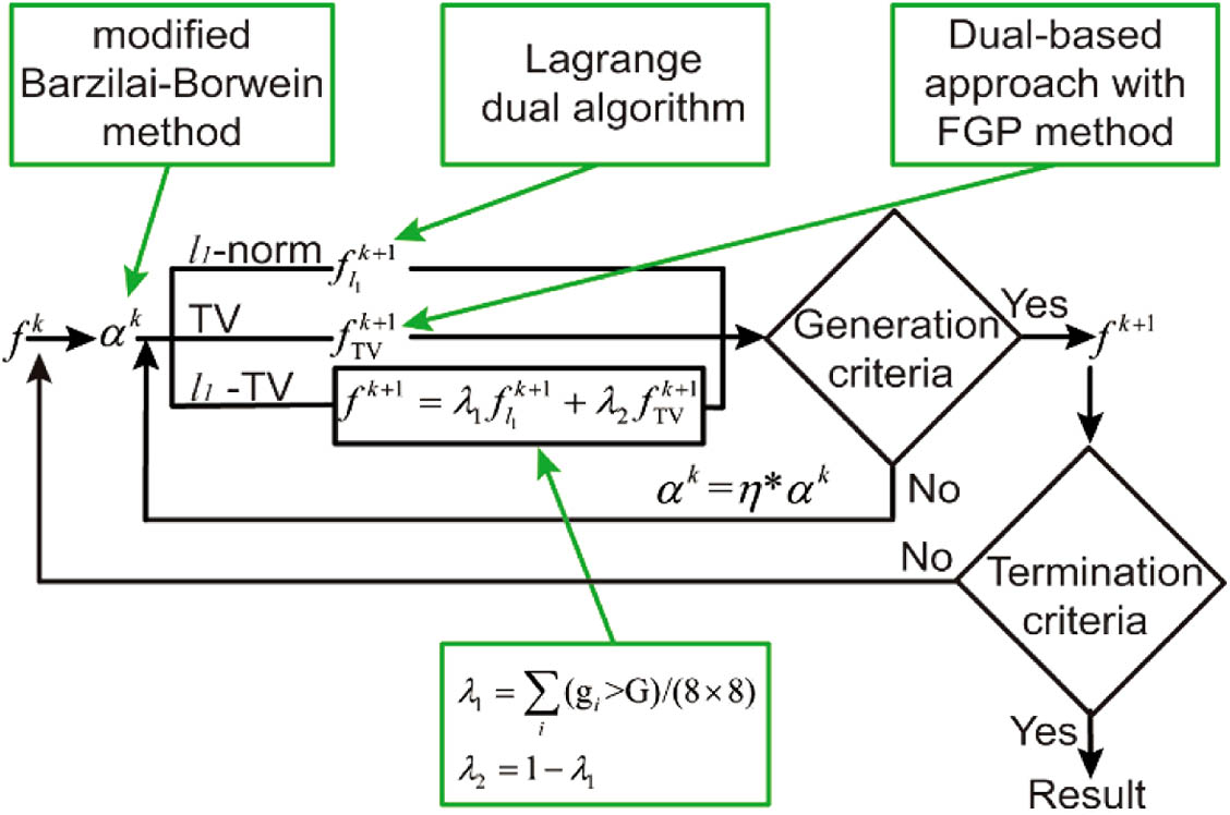
Fig. 1. SPIRAL algorithm using the l 1 l 1
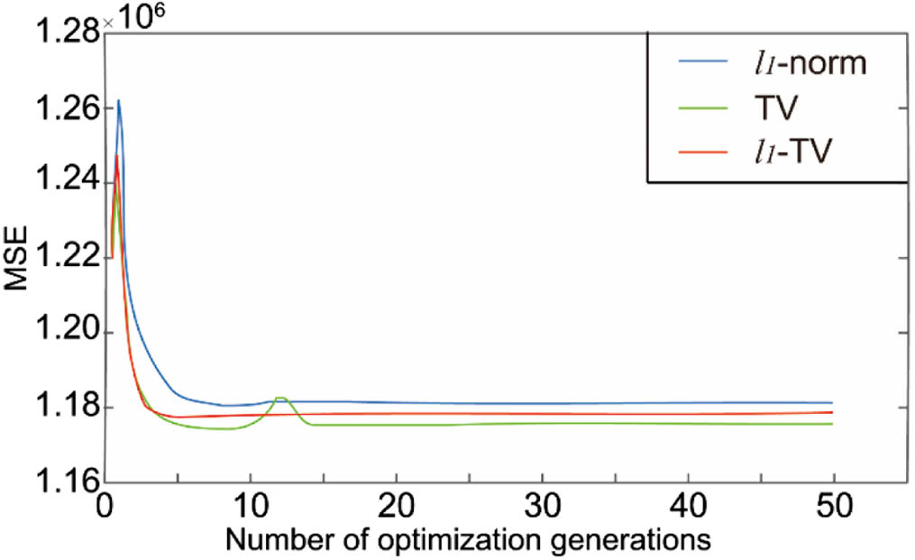
Fig. 2. MSE convergence profiles of the l 1 l 1
Fig. 3. RMSEs of the reconstructed images using the l 1 l 1
Fig. 4. Comparison of three groups of reconstructed images using different penalties. From left to right are ground truth (GT), l 1 l 1
Fig. 5. Comparison of reconstructed depth information using different penalties. From left to right are ground truth (GT), l 1 l 1
Fig. 6. Schematic of experimental system. A repetitive pulsed laser is modulated by a digital micromirror device (DMD) and raster-scans the object pixel by pixel. The reflected photons from the object arrive at a photomultiplier tube (PMT) and trigger a photon-arrival event according to the photon detection probability. The first-photon data are then recorded by a time-correlated single-photon counting (TCSPC) module and transferred to a computer for image reconstruction.
Fig. 7. Comparison of experimental results yielded by different approaches. From left to right are photon counting (PC), l 1 l 1
Fig. 8. Comparison of experimentally reconstructed depth information using different penalties. From left to right are ground truth (GT), l 1 l 1

Set citation alerts for the article
Please enter your email address
© Copyright 2018-2021 | Chinese Laser Press. All Rights Reserved 沪ICP备15018463号-20