• Acta Optica Sinica
  • Vol. 41, Issue 18, 1812001 (2021)
Min Fu1、*, Fan Chen1、2, Ge Zhu2, Hailin Shi1、2, Xiaobo Wei1、2, Junhong Qiao1、2, and Congyang Leng1、2
Author Affiliations
  • 1Engineering Research Center of Mechanical Testing Technology and Equipment (Ministry of Education), Chongqing Key Laboratory of Time-Grating Sensing and Advanced Testing Technology, Chongqing University of Technology, Chongqing 400054, China
  • 2College of Mechanical Engineering, Chongqing University of Technology, Chongqing 400054, China
  • show less
    DOI: 10.3788/AOS202141.1812001 Cite this Article Set citation alerts
    Min Fu, Fan Chen, Ge Zhu, Hailin Shi, Xiaobo Wei, Junhong Qiao, Congyang Leng. High-Precision Angular Displacement Measurement Based on Rotating Optical Field[J]. Acta Optica Sinica, 2021, 41(18): 1812001 Copy Citation Text show less
    Construction principle of rotating light field. (a) Schematic diagram of spatial modulation of light intensity; (b) composite diagram of traveling wave signal
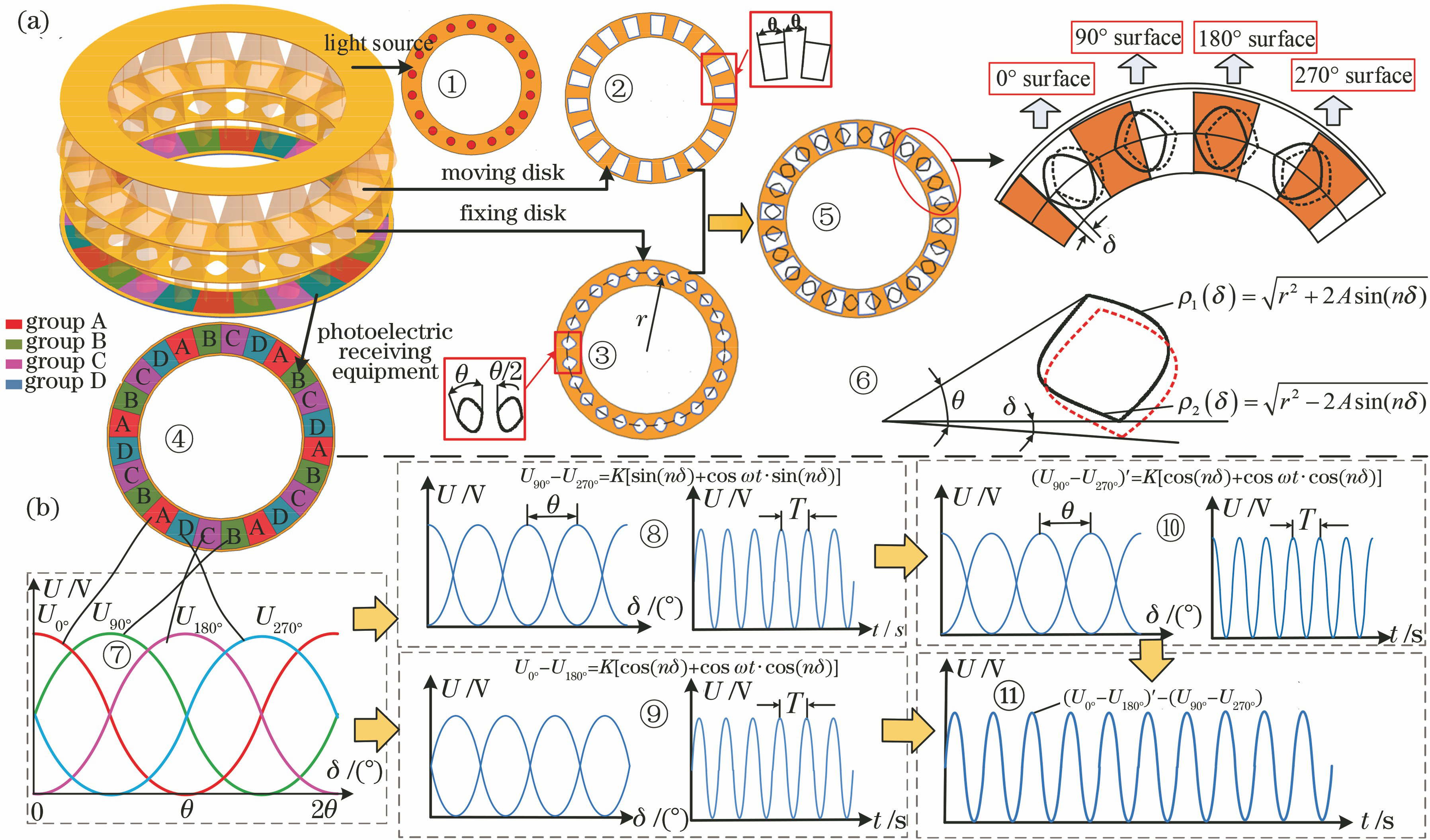
    Fig. 1. Construction principle of rotating light field. (a) Schematic diagram of spatial modulation of light intensity; (b) composite diagram of traveling wave signal
    Sensor output signal processing diagram
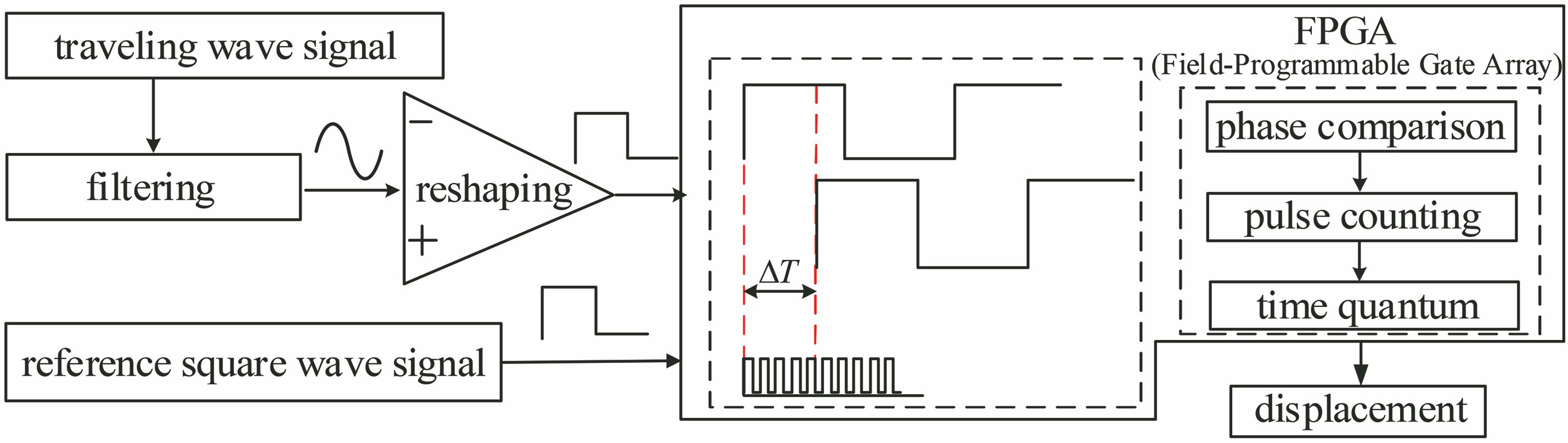
    Fig. 2. Sensor output signal processing diagram
    Experimental platform. (a) Test platform; (b) detail of sensor prototype
    Fig. 3. Experimental platform. (a) Test platform; (b) detail of sensor prototype
    Experimental results of standing wave signal and traveling wave signal. (a) Standing wave signal; (b) traveling wave signal
    Fig. 4. Experimental results of standing wave signal and traveling wave signal. (a) Standing wave signal; (b) traveling wave signal
    Experimental results. (a) Intra-level measurement error and harmonic component; (b) whole circle error curve
    Fig. 5. Experimental results. (a) Intra-level measurement error and harmonic component; (b) whole circle error curve
    Grid layout mode. (a) Whole circle uniform layout; (b) non-circular uniform layout
    Fig. 6. Grid layout mode. (a) Whole circle uniform layout; (b) non-circular uniform layout
    Models of grid surface of moving disk and fixing disk. (a) 18 pairs; (b) 90 pairs
    Fig. 7. Models of grid surface of moving disk and fixing disk. (a) 18 pairs; (b) 90 pairs
    Photoelectric signals, traveling wave signals and error frequency figures. (a) 18 pairs; (b) 90 pairs
    Fig. 8. Photoelectric signals, traveling wave signals and error frequency figures. (a) 18 pairs; (b) 90 pairs
    Physical drawing of 90 pairs of grid surfaces and experimental results. (a) Physical drawing; (b) intra-level measurement error and harmonic component
    Fig. 9. Physical drawing of 90 pairs of grid surfaces and experimental results. (a) Physical drawing; (b) intra-level measurement error and harmonic component
    Whole period error curves. (a) Whole circle uniform layout; (b) non-circular uniform layout
    Fig. 10. Whole period error curves. (a) Whole circle uniform layout; (b) non-circular uniform layout
    Angular displacementmeasurement methodBased on rotating optical fieldBased on circular gratingBased on rotary transformer
    1890l=18000l=360001632
    Accuracy /(″)±8.9±5.0±2.69±1.0±25±30
    Table 1. Comparison of measuring errors of three different angular displacement measurement devices
    Min Fu, Fan Chen, Ge Zhu, Hailin Shi, Xiaobo Wei, Junhong Qiao, Congyang Leng. High-Precision Angular Displacement Measurement Based on Rotating Optical Field[J]. Acta Optica Sinica, 2021, 41(18): 1812001
    Download Citation