• Infrared and Laser Engineering
  • Vol. 51, Issue 3, 20210821 (2022)
Nan Chen, Jiqing Zhang, Wenbiao Mao, Xiongjun Li, Linwei Song, Ling Gao, and Libin Yao*
Author Affiliations
  • Kunming Institute of Physics, Kunming 650223, China
  • show less
    DOI: 10.3788/IRLA20210821 Cite this Article
    Nan Chen, Jiqing Zhang, Wenbiao Mao, Xiongjun Li, Linwei Song, Ling Gao, Libin Yao. High-dynamic-range and high-sensitivity IRFPA digital-pixel ROIC technology (Invited)[J]. Infrared and Laser Engineering, 2022, 51(3): 20210821 Copy Citation Text show less
    Analog pixel circuit (direct injection structure)
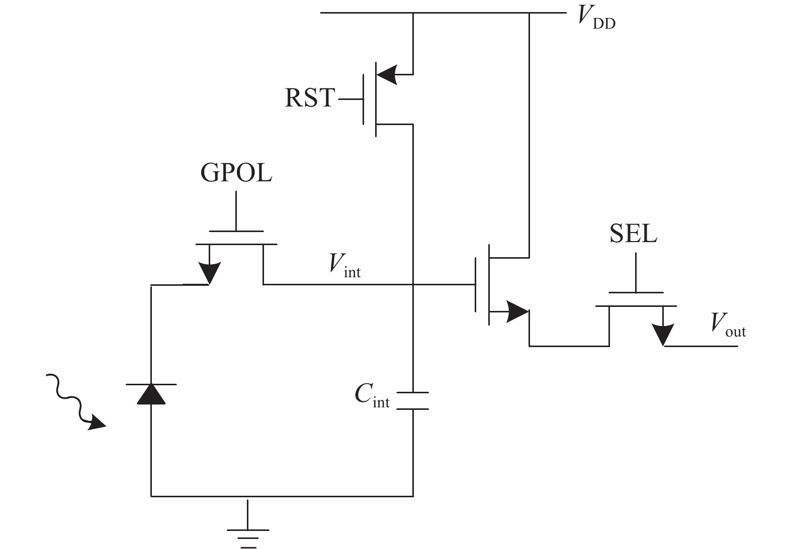
    Fig. 1. Analog pixel circuit (direct injection structure)
    Principle diagram of analog integration
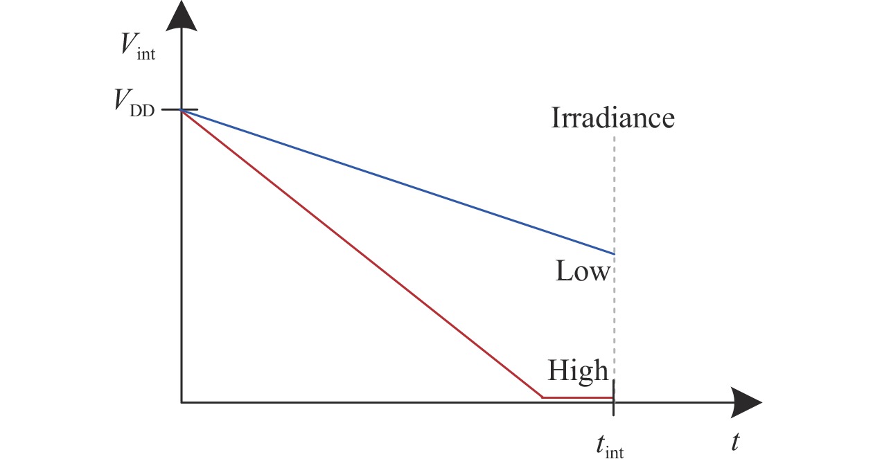
    Fig. 2. Principle diagram of analog integration
    Digital pixel circuit
    Fig. 3. Digital pixel circuit
    Digital integration
    Fig. 4. Digital integration
    Digital pixel ROIC diagram
    Fig. 5. Digital pixel ROIC diagram
    PWM digital pixel diagram and working principle
    Fig. 6. PWM digital pixel diagram and working principle
    Designed digital pixel diagram
    Fig. 7. Designed digital pixel diagram
    Timing diagram of digital pixel
    Fig. 8. Timing diagram of digital pixel
    Comparator circuits
    Fig. 9. Comparator circuits
    Layout of digital pixel
    Fig. 10. Layout of digital pixel
    Simulation results of digital pixel: (a) Pulse frequency; (b) Digital output
    Fig. 11. Simulation results of digital pixel: (a) Pulse frequency; (b) Digital output
    The surface morphology of LW HgCdTe epilayers
    Fig. 12. The surface morphology of LW HgCdTe epilayers
    LW 384×288 digital-pixel IRFPA detector chip
    Fig. 13. LW 384×288 digital-pixel IRFPA detector chip
    LW 256×256 digital-pixel IRFPA detector chip
    Fig. 14. LW 256×256 digital-pixel IRFPA detector chip
    LW 384×288 digital-pixel IRFPA detector module
    Fig. 15. LW 384×288 digital-pixel IRFPA detector module
    Sample image of LW 384×288 digital-pixel detector
    Fig. 16. Sample image of LW 384×288 digital-pixel detector
    NETD of LW 384×288 digital-pixel detector (tint = 9 ms)
    Fig. 17. NETD of LW 384×288 digital-pixel detector (tint = 9 ms)
    NETD of LW 384×288 digital-pixel detector (tint = 33 ms)
    Fig. 18. NETD of LW 384×288 digital-pixel detector (tint = 33 ms)
    NETD of LW 256×256 digital-pixel detector (tint = 38 ms)
    Fig. 19. NETD of LW 256×256 digital-pixel detector (tint = 38 ms)
    Dynamic range measurement system for detector (a) and high temperature black body (b)
    Fig. 20. Dynamic range measurement system for detector (a) and high temperature black body (b)
    Noise of LW 384×288 digital-pixel detector (tint = 9 ms)
    Fig. 21. Noise of LW 384×288 digital-pixel detector (tint = 9 ms)
    Noise of LW 256×256 digital-pixel detector (tint = 9 ms)
    Fig. 22. Noise of LW 256×256 digital-pixel detector (tint = 9 ms)
    Heater and soldering iron for thermal imaging test
    Fig. 23. Heater and soldering iron for thermal imaging test
    Thermal image captured by LW 384×288 digital pixel detector
    Fig. 24. Thermal image captured by LW 384×288 digital pixel detector
    ReferenceSofradir/CEA LetiMIT Lincoln laboratorySITPThis workThis work
    * After background subtraction
    Detecor materialHgCdTeN.A.HgCdTeHgCdTeHgCdTe
    Resolution320×256256×256512×32256×256384×288
    Pixel pitch25 µm30 µm30 µm30 µm25 µm
    Cut-off wavelength9.2 μmN.A.10.5 μm9.5 μm9.5 μm
    F# F/1.3 N.A.F/2 F/2 F/2
    Peak NETD2 mK(@22 ms)N.A.8 mK(@41 ms)1.9 mK(@38 ms)3.4 mK(@33 ms)
    ADC resolution1517161616
    Dynamic range90 dB114 dB*85 dB98 dB96 dB
    Chip power consumption150 mW30 mW117 mW63 mW113 mW
    Power consumption per pixel1.8 μW0.5 μW7.1 μW1.0 μW1.0 μW
    Table 1. Comparison of different digital-pixel LW IRFPA detectors
    Nan Chen, Jiqing Zhang, Wenbiao Mao, Xiongjun Li, Linwei Song, Ling Gao, Libin Yao. High-dynamic-range and high-sensitivity IRFPA digital-pixel ROIC technology (Invited)[J]. Infrared and Laser Engineering, 2022, 51(3): 20210821
    Download Citation