• Laser & Optoelectronics Progress
  • Vol. 61, Issue 1, 0126001 (2024)
Yan Zhang†、* and Tong Nan1、†
Author Affiliations
  • Beijing Key Laboratory of Metamaterials and Devices, Department of Physics, Capital Normal University, Beijing 100048, China
  • show less
    DOI: 10.3788/LOP232183 Cite this Article Set citation alerts
    Yan Zhang, Tong Nan. Generations of Structured Light (Invited)[J]. Laser & Optoelectronics Progress, 2024, 61(1): 0126001 Copy Citation Text show less
    Different types of structured light beams
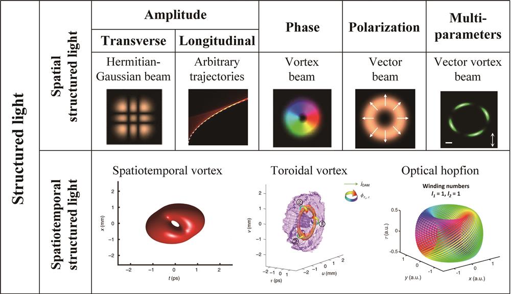
    Fig. 1. Different types of structured light beams
    Generation of ultrasmall non-diffractive light fields with axially uniform and oscillating intensities using single-layer dielectric metalens
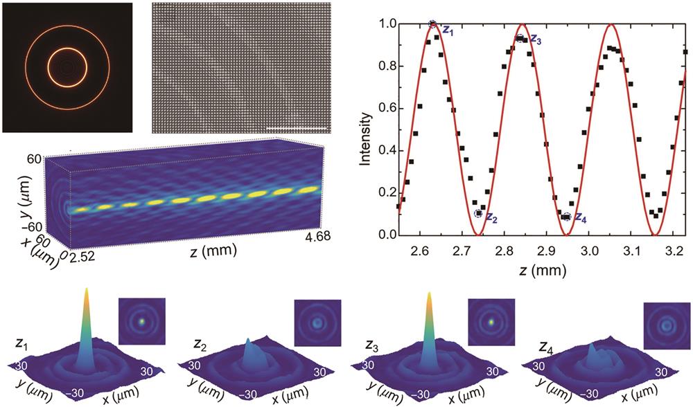
    Fig. 2. Generation of ultrasmall non-diffractive light fields with axially uniform and oscillating intensities using single-layer dielectric metalens
    Generation of Bessel-like beam. (a) Diffractive optical element with the period P and the track of the zero-order Bessel beam peak behind the diffractive optical element; (b) rays emitted from expanding circles on the input plane intersect on the specified focal curve; (c) realization of a 2D sine beam and a helical beam based on the 1D sine beam
    Fig. 3. Generation of Bessel-like beam. (a) Diffractive optical element with the period P and the track of the zero-order Bessel beam peak behind the diffractive optical element; (b) rays emitted from expanding circles on the input plane intersect on the specified focal curve; (c) realization of a 2D sine beam and a helical beam based on the 1D sine beam
    Generation and characterization of terahertz ring-Airy beam. (a) Designed ring-Airy meta-hologram with a partial optical image in the inset; (b) experimental setup for characterizing the intensity distribution of the generated ring-Airy field; (c) experimental intensity distributions on the initial plane at a frequency of 0.8 THz; (d) vertical view of the THz ring-Airy beam propagation on the x-z plane from the experiment
    Fig. 4. Generation and characterization of terahertz ring-Airy beam. (a) Designed ring-Airy meta-hologram with a partial optical image in the inset; (b) experimental setup for characterizing the intensity distribution of the generated ring-Airy field; (c) experimental intensity distributions on the initial plane at a frequency of 0.8 THz; (d) vertical view of the THz ring-Airy beam propagation on the x-z plane from the experiment
    Generation of single and array self-accelerating beams based on synthetic phase method. (a) Schematics of simple and synthetic phase profiles and synthetic-phase all-dielectric metasurfaces for generating twodimensional Airy optical beams; (b) schematics of added phase profiles, all-dielectric metasurfaces used to generate a single cosine-oscillation Bessel-like beam, and an array of such beams
    Fig. 5. Generation of single and array self-accelerating beams based on synthetic phase method. (a) Schematics of simple and synthetic phase profiles and synthetic-phase all-dielectric metasurfaces for generating twodimensional Airy optical beams; (b) schematics of added phase profiles, all-dielectric metasurfaces used to generate a single cosine-oscillation Bessel-like beam, and an array of such beams
    Generation of different transverse Gaussian modes. (a) Gaussian family of modes; (b) controlled rotation of HG31 mode; (c) the IG modes with different ellipticity; (d) intensity distributions of the LG beams with p=3 and p=10 and corresponding HG modes; (e) experimental results: broadband performance of meta-converters
    Fig. 6. Generation of different transverse Gaussian modes. (a) Gaussian family of modes; (b) controlled rotation of HG31 mode; (c) the IG modes with different ellipticity; (d) intensity distributions of the LG beams with p=3 and p=10 and corresponding HG modes; (e) experimental results: broadband performance of meta-converters
    Schematic diagrams of generating non-diffracting beams via spectral phase modulation. (a) Spectral phase modulation; (b) caustics with specific structure
    Fig. 7. Schematic diagrams of generating non-diffracting beams via spectral phase modulation. (a) Spectral phase modulation; (b) caustics with specific structure
    Different methods to generate vortex beams. (a) π/2 converter; (b) SPP; (c) fork grating hologram; (d) spiral zone plate
    Fig. 8. Different methods to generate vortex beams. (a) π/2 converter; (b) SPP; (c) fork grating hologram; (d) spiral zone plate
    Generation of vortex beams with different orders in the terahertz range using metasurfaces. (a) A complementary V-shaped antenna phase modulation unit; (b) eight kinds of complementary V-shaped antenna structures corresponding to phase shifts from -3π/4 to π with a π/4 interval; (c) (d) the photographs of the central parts of two designed VPPs with l=2 and l=3; (e) (f) the measured vortex phase distributions with l=2 and l=3; (g) (h) the simulated vortex phase distributions with l=2 and l=3
    Fig. 9. Generation of vortex beams with different orders in the terahertz range using metasurfaces. (a) A complementary V-shaped antenna phase modulation unit; (b) eight kinds of complementary V-shaped antenna structures corresponding to phase shifts from -3π/4 to π with a π/4 interval; (c) (d) the photographs of the central parts of two designed VPPs with l=2 and l=3; (e) (f) the measured vortex phase distributions with l=2 and l=3; (g) (h) the simulated vortex phase distributions with l=2 and l=3
    PB phase element system for generating perfect vortex beams and experimental generation of perfect vortex beams
    Fig. 10. PB phase element system for generating perfect vortex beams and experimental generation of perfect vortex beams
    Generation of fractional order vortex beam. (a) Geometry and notation of the spiral slit for achieving an anomalous Bessel vortex beam; (b) schematic principle for metasurface-based versatile generation of OAM carrying integer and fractional modes engineered by polarization modulation; (c) generation of the phase mask; (d) fractional elliptic perfect optical vortex modes with different gap positions
    Fig. 11. Generation of fractional order vortex beam. (a) Geometry and notation of the spiral slit for achieving an anomalous Bessel vortex beam; (b) schematic principle for metasurface-based versatile generation of OAM carrying integer and fractional modes engineered by polarization modulation; (c) generation of the phase mask; (d) fractional elliptic perfect optical vortex modes with different gap positions
    Generation of composite vortex beam. (a) Generation of concentric electron vortex beams and the measurement of their topological charges; (b) schematic of the approach for composite vortex beams generation using a single metasurface; (c) schematic of the approach for the superposition of grafted perfect vortex beams in multiple channels with a single metasurface
    Fig. 12. Generation of composite vortex beam. (a) Generation of concentric electron vortex beams and the measurement of their topological charges; (b) schematic of the approach for composite vortex beams generation using a single metasurface; (c) schematic of the approach for the superposition of grafted perfect vortex beams in multiple channels with a single metasurface
    Cylindrically symmetric vector light field and tight focusing characteristics. (a) Radial polarized light and azimuthally polarized light; (b) radial component light intensity and polarization state distribution diagram in a tightly focused light field of radially polarized light; (c) radial polarized light in a tightly focused light field longitudinal component light intensity and polarization distribution diagram
    Fig. 13. Cylindrically symmetric vector light field and tight focusing characteristics. (a) Radial polarized light and azimuthally polarized light; (b) radial component light intensity and polarization state distribution diagram in a tightly focused light field of radially polarized light; (c) radial polarized light in a tightly focused light field longitudinal component light intensity and polarization distribution diagram
    Generating vector beam based on SLM. (a) Schematic of experimental setup; (b) generated single-mode vector beams under different initial phases; (c) Poincar'e sphere Σ and different states of polarization on Poincar'e sphere; (d) the experimentally generated four different vector fields
    Fig. 14. Generating vector beam based on SLM. (a) Schematic of experimental setup; (b) generated single-mode vector beams under different initial phases; (c) Poincar'e sphere Σ and different states of polarization on Poincar'e sphere; (d) the experimentally generated four different vector fields
    Higher-order Poincaré sphere and generalized Poincaré sphere. (a) Higher-order Poincaré sphere representation for 𝓁≠σ,𝓁=+1; (b) higher-order Poincaré sphere representation for 𝓁=σ,𝓁=-1; (c) G sphere for m=1; (d) experimentally generated vector fields described in the G sphere
    Fig. 15. Higher-order Poincaré sphere and generalized Poincaré sphere. (a) Higher-order Poincaré sphere representation for 𝓁σ,𝓁=+1; (b) higher-order Poincaré sphere representation for 𝓁=σ,𝓁=-1; (c) G sphere for m=1; (d) experimentally generated vector fields described in the G sphere
    Generation of nondiffracting Bessel beams with polarization state that varies with propagation distance. (a) Line focus with an axicon; (b) producing two linear orthogonal polarization states along the propagation distance; (c) line focus with continuous variation of the state of polarization along the propagation distance; (d) schematic of experimental setup; (e) experimental generation of nondiffracting Bessel beams with polarization variation along propagation distance
    Fig. 16. Generation of nondiffracting Bessel beams with polarization state that varies with propagation distance. (a) Line focus with an axicon; (b) producing two linear orthogonal polarization states along the propagation distance; (c) line focus with continuous variation of the state of polarization along the propagation distance; (d) schematic of experimental setup; (e) experimental generation of nondiffracting Bessel beams with polarization variation along propagation distance
    Generation of nondiffracting beams with axial uniform intensity and polarization variation along the longitudinal axis. (a) Schematic of reshaping the axial intensity distributions of quasi-Bessel beams; (b) illustration of constructing polarization oscillating beams
    Fig. 17. Generation of nondiffracting beams with axial uniform intensity and polarization variation along the longitudinal axis. (a) Schematic of reshaping the axial intensity distributions of quasi-Bessel beams; (b) illustration of constructing polarization oscillating beams
    Generation of structured light beams with polarization variation along propagation using metasurfaces. (a) Schematic of the multi-foci metalens with polarization-rotated focal points; (b) schematic of the metalens with customized focal curve and polarization profile in 3D space; (c) 3D vector beam generation based on metasurface; (d) schematic of structured light beams with polarization variation along the propagation path generated using metasurfaces
    Fig. 18. Generation of structured light beams with polarization variation along propagation using metasurfaces. (a) Schematic of the multi-foci metalens with polarization-rotated focal points; (b) schematic of the metalens with customized focal curve and polarization profile in 3D space; (c) 3D vector beam generation based on metasurface; (d) schematic of structured light beams with polarization variation along the propagation path generated using metasurfaces
    Concept of longitudinally variable polarization elements
    Fig. 19. Concept of longitudinally variable polarization elements
    Generation of radially polarized Lorentz beams and vector vortex beams. (a) Schematic principle for converting a right circularly polarized uniform plane wave to a radially polarized Lorentz wave and schematic view of cross antenna in each unit; (b) schematic illustration of the hybrid-order Poincaré sphere, experimental setup to generate arbitrary vector vortex beams on the hybrid-order Poincaré sphere and schematic illustration of generating a vector vortex beam
    Fig. 20. Generation of radially polarized Lorentz beams and vector vortex beams. (a) Schematic principle for converting a right circularly polarized uniform plane wave to a radially polarized Lorentz wave and schematic view of cross antenna in each unit; (b) schematic illustration of the hybrid-order Poincaré sphere, experimental setup to generate arbitrary vector vortex beams on the hybrid-order Poincaré sphere and schematic illustration of generating a vector vortex beam
    Generation of perfect vector vortex beams and perfect Poincaré beams. (a) Generation of perfect vector vortex beams using a single-layer metasurface; (b) principle of generation of generalized perfect Poincaré beams via dielectric metasurface
    Fig. 21. Generation of perfect vector vortex beams and perfect Poincaré beams. (a) Generation of perfect vector vortex beams using a single-layer metasurface; (b) principle of generation of generalized perfect Poincaré beams via dielectric metasurface
    Generation of time-varying OAM and vector spatiotemporal beams. (a) Experimental scheme for generating and measuring light beams with a self-torque; (b) simplified schematic of a device capable of mapping an input vector spatiotemporal field onto an arbitrary vector spatiotemporal output field
    Fig. 22. Generation of time-varying OAM and vector spatiotemporal beams. (a) Experimental scheme for generating and measuring light beams with a self-torque; (b) simplified schematic of a device capable of mapping an input vector spatiotemporal field onto an arbitrary vector spatiotemporal output field
    Generation of spatiotemporal optical vortex beams. (a) Experimental schematic for generating spatiotemporal optical vortices; (b) generation of ultrafast spatiotemporal wave packet embedded with time-varying OAM; (c) intensity and phase information of an experimentally generated photonic toroidal vortex
    Fig. 23. Generation of spatiotemporal optical vortex beams. (a) Experimental schematic for generating spatiotemporal optical vortices; (b) generation of ultrafast spatiotemporal wave packet embedded with time-varying OAM; (c) intensity and phase information of an experimentally generated photonic toroidal vortex
    Schematic of spatiotemporal beams carrying two forms of OAM
    Fig. 24. Schematic of spatiotemporal beams carrying two forms of OAM
    Yan Zhang, Tong Nan. Generations of Structured Light (Invited)[J]. Laser & Optoelectronics Progress, 2024, 61(1): 0126001
    Download Citation