
Yingying Zhang, Shiqiang Xia, Xingdong Zhao, Lu Qin, Xuejing Feng, Wenrong Qi, Yajing Jiang, Hai Lu, Daohong Song, Liqin Tang, Zunlue Zhu, Wuming Liu, Yufang Liu, "Symmetry-protected third-order exceptional points in staggered flatband rhombic lattices," Photonics Res. 11, 225 (2023)
- Photonics Research
- Vol. 11, Issue 2, 225 (2023)
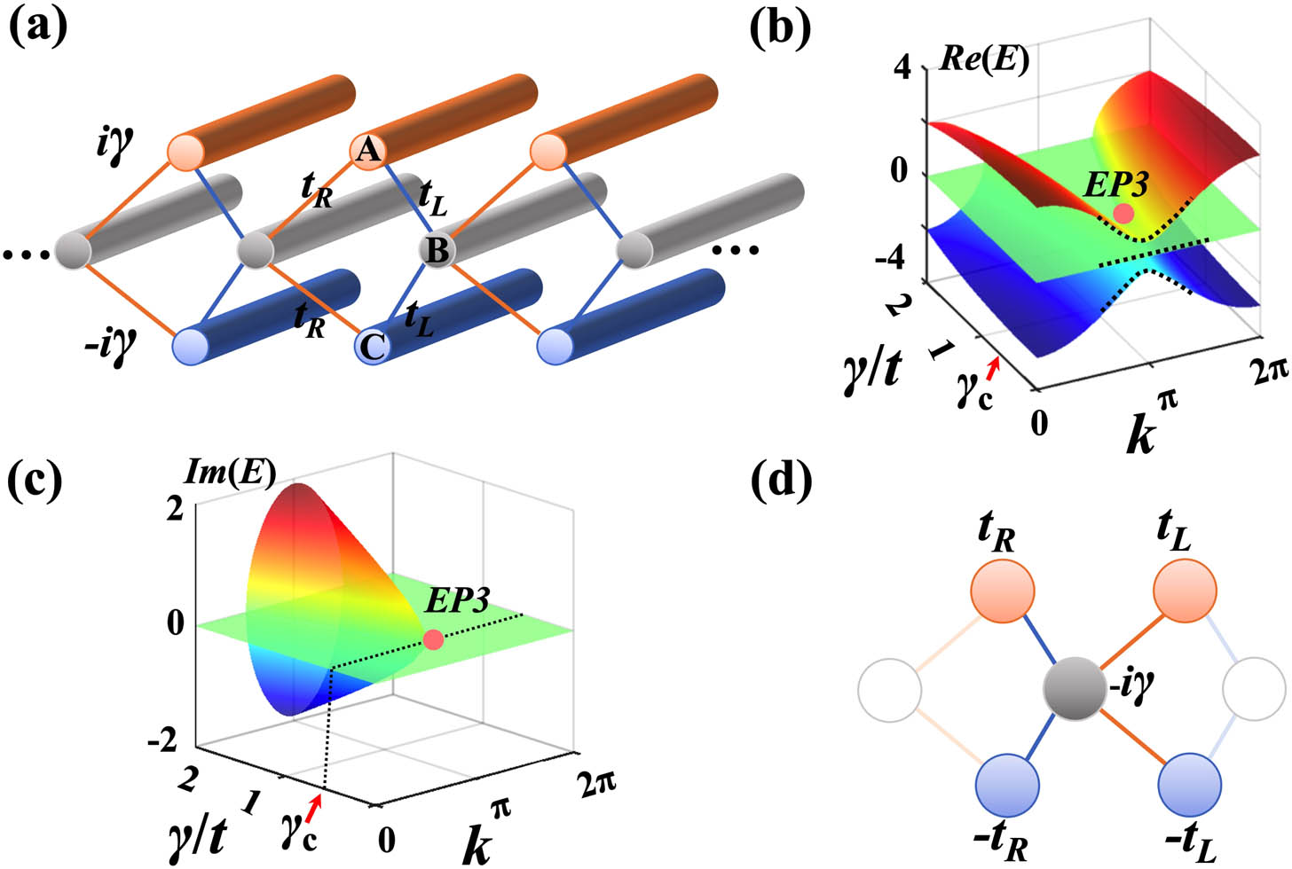
Fig. 1. (a) Schematic of the diagonal PT γ A loss − γ C B t L = t ( 1 + g ) t R = t ( 1 − g ) 0 ≤ g < 1 t g = 0 l = 1 γ / t g = 0.2 γ c / t = 0.56
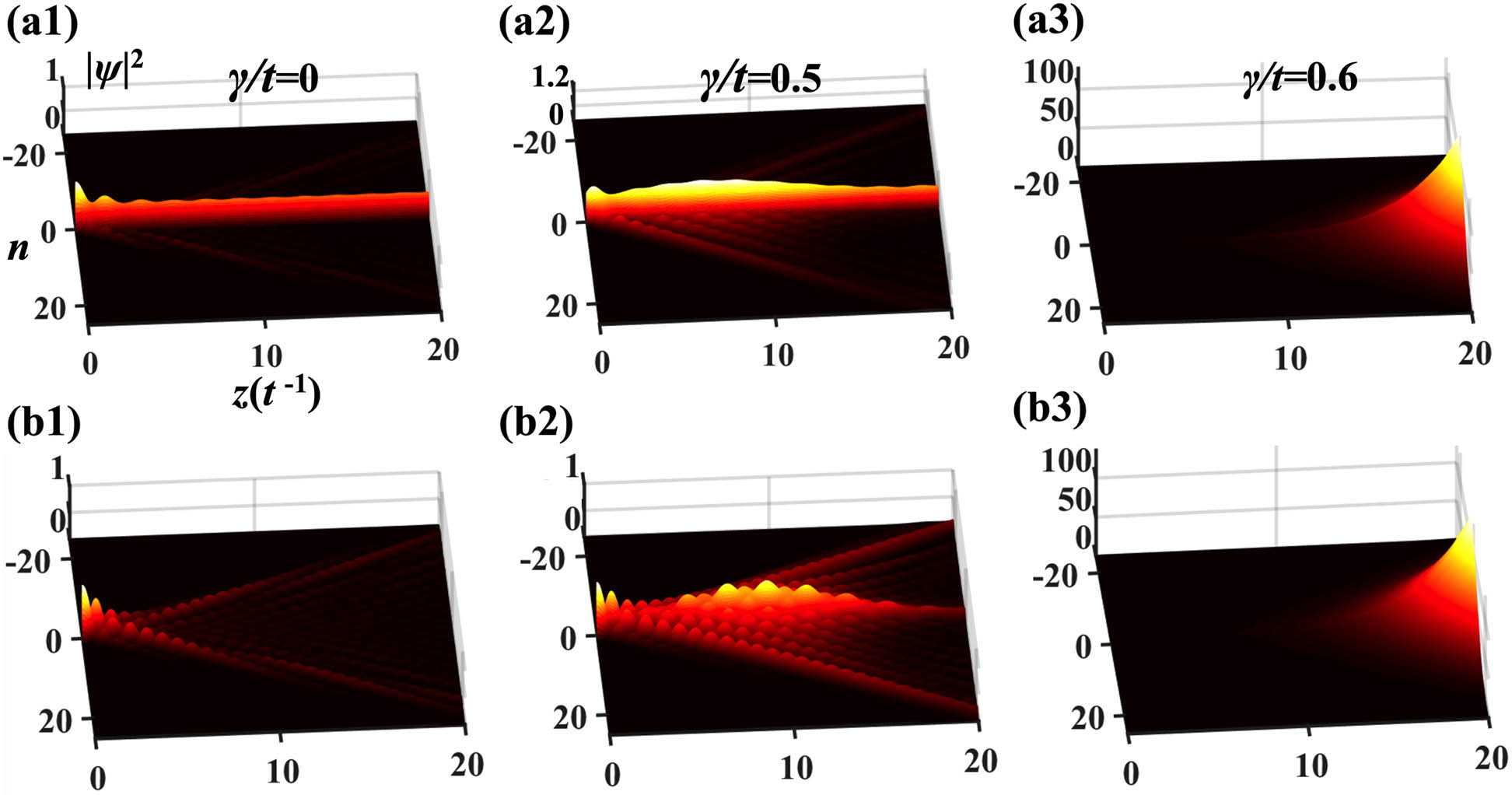
Fig. 2. Intensity profile | ψ | 2 A B A γ / t = 0 γ / t = 0.5 PT γ / t = 0.6 B γ / t = 0 γ / t = 0.5 γ / t = 0.6 z = 20 t − 1
Fig. 3. (a), (b) Analytical (dashed lines) and numerical (solid lines) results for the (a) real and (b) imaginary parts of the spectrum as a function of the detuning ϵ / t E − 1 E 0 E 1 E 0 − E 1 = Δ E
Fig. 4. (a), (b) Intensity profile for the B ϵ / t = 0.03 ϵ / t = 0.06 ϵ / t = 0.03 2 (b2) is obtained. (c), (d) Same as (a), (b) but for the excitation of a flatband CLS. The CLS can stay well localized despite the presence of the lattice perturbations.
Fig. 5. (a) Schematic of the off-diagonal PT T L = t L + i γ T L * = t L − i γ T R = t R + i γ T R * = t R − i γ t L t R 1 (a), which represent conserved staggered couplings. (b), (c) Calculated (b) real and (c) imaginary parts of the spectrum as a function of γ / t g = 0.2 k = 0 γ c = t A C
Fig. 6. Same as Fig. 2 , but for the off-diagonal PT A γ / t = 0.45 γ / t = 0.9 PT γ / t = 1.001 B γ / t PT
Fig. 7. Same as Fig. 3 , but for the off-diagonal PT
Fig. 8. Same as Fig. 4 , but for the off-diagonal PT
Fig. 9. Energy evolution in the symmetry-broken phase of the (a) diagonal and (b)–(d) off-diagonal PT A B [ P ( z ) = e 0.39 z ] A B [ P ( z ) ∼ z 4 ] P 1 / 4
Fig. 10. (a) Intensity profile | ψ | 2 B γ / t = 0.98 γ / t ν γ / t z = 20 t − 1 ν t


Set citation alerts for the article
Please enter your email address

© Copyright 2018-2021 | Chinese Laser Press. All Rights Reserved 沪ICP备15018463号-20