• Chinese Optics Letters
  • Vol. 20, Issue 2, 021405 (2022)
Yang Gao1、*, Jiali Liao2、3, Jun Xu1, and Zhanrong Zhou1、**
Author Affiliations
  • 1Xi’an Research Institute of High Technology, Xi’an 710025, China
  • 2School of Physics and Optoelectronic Engineering, Xidian University, Xi’an 710071, China
  • 3State Key Laboratory of Pulsed Power Laser Technology, Hefei 230037, China
  • show less
    DOI: 10.3788/COL202220.021405 Cite this Article Set citation alerts
    Yang Gao, Jiali Liao, Jun Xu, Zhanrong Zhou. Sidelobe suppression for coherent beam combining with laser beams placed along a Fermat spiral[J]. Chinese Optics Letters, 2022, 20(2): 021405 Copy Citation Text show less
    Laser beams with different tiled-aperture geometries and the corresponding far-field intensity distributions. (a) The hexagon array, (b) the square array, (c) the FS array, (d) the far-field intensity distribution of the hexagon array, (e) the far-field intensity distribution of the square array, (f) the far-field intensity distribution of the FS array, and (g) the intensity variations along the transverse axis that include both the maximum of the main lobe and of the largest secondary lobes. The beam numbers of (a), (b), and (c) are 91, 100, and 100, respectively. In this simulation, the diameter of the sub-aperture is 0.7 mm, and the distance between the tiled-aperture and the interference pattern is 350 m.
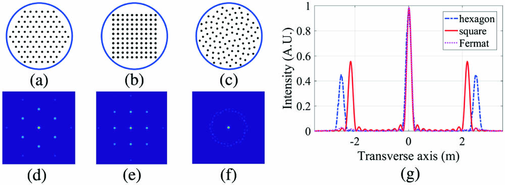
    Fig. 1. Laser beams with different tiled-aperture geometries and the corresponding far-field intensity distributions. (a) The hexagon array, (b) the square array, (c) the FS array, (d) the far-field intensity distribution of the hexagon array, (e) the far-field intensity distribution of the square array, (f) the far-field intensity distribution of the FS array, and (g) the intensity variations along the transverse axis that include both the maximum of the main lobe and of the largest secondary lobes. The beam numbers of (a), (b), and (c) are 91, 100, and 100, respectively. In this simulation, the diameter of the sub-aperture is 0.7 mm, and the distance between the tiled-aperture and the interference pattern is 350 m.
    Far-field intensity distributions caused by the FS arrays with different laser beam numbers.
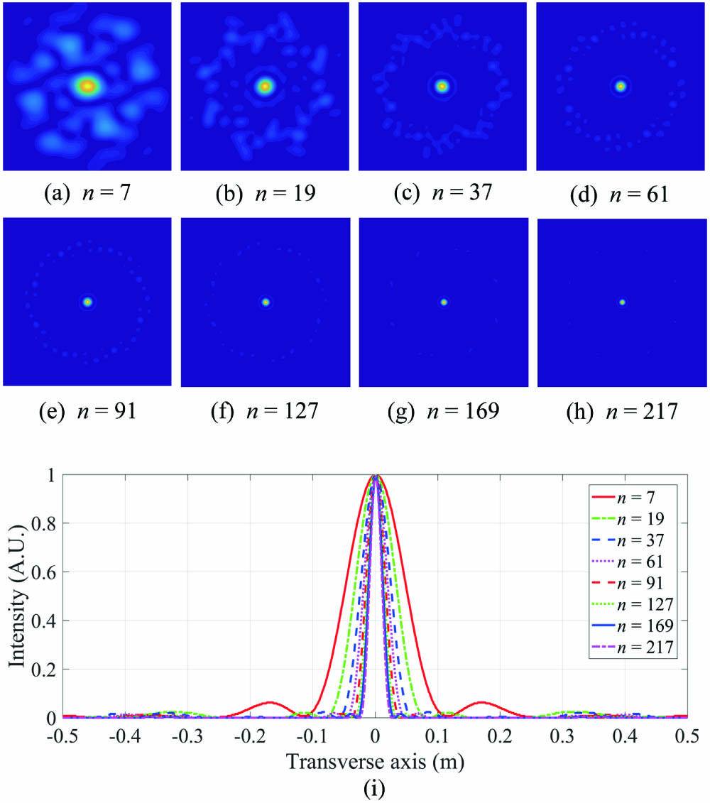
    Fig. 2. Far-field intensity distributions caused by the FS arrays with different laser beam numbers.
    Effect of the laser beam diameter on the sidelobe suppression. When the laser beam diameter ranges from 10 pixels to 45 pixels and the distance parameter s is equal to 50 pixels, (a) the main lobe intensity I0 and (b) the peak intensity ratio η are investigated, with the number of the laser beams as 7, 19, and 37, respectively.
    Fig. 3. Effect of the laser beam diameter on the sidelobe suppression. When the laser beam diameter ranges from 10 pixels to 45 pixels and the distance parameter s is equal to 50 pixels, (a) the main lobe intensity I0 and (b) the peak intensity ratio η are investigated, with the number of the laser beams as 7, 19, and 37, respectively.
    Effect of the distance parameter s on the sidelobe suppression. When the distance parameter s ranges from 30 pixels to 70 pixels and the laser beam diameter is equal to 25 pixels, (a) the main lobe intensity I0 and (b) the peak intensity ratio η are investigated, with the total number of the laser beams as 7, 19, and 37, respectively.
    Fig. 4. Effect of the distance parameter s on the sidelobe suppression. When the distance parameter s ranges from 30 pixels to 70 pixels and the laser beam diameter is equal to 25 pixels, (a) the main lobe intensity I0 and (b) the peak intensity ratio η are investigated, with the total number of the laser beams as 7, 19, and 37, respectively.
    Effect of the fill factor on the sidelobe suppression. When the distance parameter s ranges from 30 pixels to 70 pixels and the laser beam diameter is half the parameter s, (a) the main lobe intensity I0 and (b) the peak intensity ratio η are investigated, with the total number of the laser beams as 7, 19, and 37, respectively.
    Fig. 5. Effect of the fill factor on the sidelobe suppression. When the distance parameter s ranges from 30 pixels to 70 pixels and the laser beam diameter is half the parameter s, (a) the main lobe intensity I0 and (b) the peak intensity ratio η are investigated, with the total number of the laser beams as 7, 19, and 37, respectively.
    Investigation of (a) the fill factor, (b) the main lobe intensity, and (c) the peak intensity ratio for three different kinds of laser beam arrays, assuming that the distance parameter s in the FS array, the spatial period of the hexagon/square array, and the laser beam diameter are 25 pixels, 30 pixels, and 20 pixels, respectively. Limited by the geometric constraints, the laser beam numbers in the hexagon array are set to be 7, 19, 37, 61, and 91, and the laser beam numbers in the square array are set to be 9, 16, 25, 36, 49, 64, 81, and 100. Taking advantage of the rotation symmetry, the total number in the FS array is not limited and ranges from 5 to 100 continuously in the simulation.
    Fig. 6. Investigation of (a) the fill factor, (b) the main lobe intensity, and (c) the peak intensity ratio for three different kinds of laser beam arrays, assuming that the distance parameter s in the FS array, the spatial period of the hexagon/square array, and the laser beam diameter are 25 pixels, 30 pixels, and 20 pixels, respectively. Limited by the geometric constraints, the laser beam numbers in the hexagon array are set to be 7, 19, 37, 61, and 91, and the laser beam numbers in the square array are set to be 9, 16, 25, 36, 49, 64, 81, and 100. Taking advantage of the rotation symmetry, the total number in the FS array is not limited and ranges from 5 to 100 continuously in the simulation.
    Schematic diagram of the optical system.
    Fig. 7. Schematic diagram of the optical system.
    Intensity distributions obtained by different designed FS arrays. The characteristics of the four FS arrays are listed in Table 1.
    Fig. 8. Intensity distributions obtained by different designed FS arrays. The characteristics of the four FS arrays are listed in Table 1.
    ParameterFig. 8(a)Fig. 8(b)Fig. 8(c)Fig. 8(d)
    Laser beam number244292168
    Diameter of the array (mm)21214444
    Fill factor5%9%5%9%
    Main lobe intensity (in experiment)4%9%3%9%
    Main lobe intensity (in simulation)6%13%7%17%
    Peak intensity ratio (in experiment)2323
    Peak intensity ratio (in simulation)49921
    Table 1. The Characteristics and the Image Processing Results
    Yang Gao, Jiali Liao, Jun Xu, Zhanrong Zhou. Sidelobe suppression for coherent beam combining with laser beams placed along a Fermat spiral[J]. Chinese Optics Letters, 2022, 20(2): 021405
    Download Citation