
Yang Gao, Jiali Liao, Jun Xu, Zhanrong Zhou. Sidelobe suppression for coherent beam combining with laser beams placed along a Fermat spiral[J]. Chinese Optics Letters, 2022, 20(2): 021405
- Chinese Optics Letters
- Vol. 20, Issue 2, 021405 (2022)
Abstract
1. Introduction
Because of the influence of heat damage, nonlinear effect, mode instability, and brightness of the pump source, the output power of a single laser is limited[
In most CBC systems, the apertures of the laser beams are configured as the hexagon array, the square array, and their derivative arrays[
In this Letter, we proposed an aperiodic FS tiled-aperture geometry for laser beams to suppress the sidelobe power in the CBC. This Letter is organized as follows. First, FS distribution of the laser beams is introduced, comparing the hexagon array and the square array. Second, the far-field intensity distribution is analyzed by the Kirchhoff scalar diffraction theory, and the factors that affect the sidelobe suppression are discussed in detail, including the number of the laser beams, the distance parameter, the laser beam diameter, and the fill factor. Additionally, the intensity distributions obtained by different designed arrays are investigated numerically. Finally, experiments were carried out to demonstrate the effects of the FS beam array on the sidelobe suppression in CBC.
Sign up for Chinese Optics Letters TOC. Get the latest issue of Chinese Optics Letters delivered right to you!Sign up now
2. Design and Principle
In this study, the laser beams in the CBC optical system are arranged along an FS. Thus, the distribution of the laser beam centers can be described by
We assume that all of the laser beams have the same circular aperture, and the intensity of each beam follows Gaussian distribution. Thus, the optical field distribution of the laser beam on the laser emission plane is given by
The laser array is placed in the plane, and the light propagates along the direction. According to the Kirchhoff scalar diffraction theory, the far-field optical distribution is given by
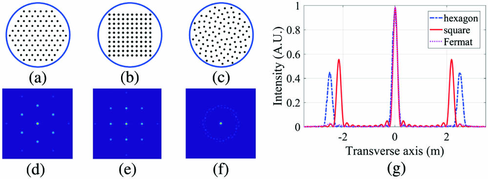
Based on the Kirchhoff scalar diffraction theory, the far-field intensity distributions of different laser arrays were calculated, and the results are shown in Fig. 1. It is clear that the sidelobes shown in Fig. 1(f) are much weaker than the sidelobes shown in Figs. 1(d) and 1(e). It denotes that the FS beam array is a promising approach for the suppression of the sidelobe power in the CBC system, compared to the hexagon array and the square array.
![]()
Figure 1.Laser beams with different tiled-aperture geometries and the corresponding far-field intensity distributions. (a) The hexagon array, (b) the square array, (c) the FS array, (d) the far-field intensity distribution of the hexagon array, (e) the far-field intensity distribution of the square array, (f) the far-field intensity distribution of the FS array, and (g) the intensity variations along the transverse axis that include both the maximum of the main lobe and of the largest secondary lobes. The beam numbers of (a), (b), and (c) are 91, 100, and 100, respectively. In this simulation, the diameter of the sub-aperture is 0.7 mm, and the distance between the tiled-aperture and the interference pattern is 350 m.
3. Analysis
In an optical CBC system, there are always sidelobes in the interference pattern, but the fraction of power encircled in those sidelobes can be significantly decreased by making proper choices. In this section, we analyze the impact of different parameters on the interference pattern lobe distribution, for example, the beam number, beam diameter, beam spacing, and filling factor. In addition, the intensity distributions obtained by different beam arrays are investigated and compared at the end of this section.
From Eqs. (1) and (2), the distance between two consecutive laser beams is set according to the FS, which naturally satisfied the condition of sidelobe suppression. As a result, the sidelobes were suppressed by the FS beam array significantly, in contrast to the periodic arrays, such as the hexagon array and the square array. The far-field intensity distributions obtained by the FS beam arrays with different numbers of laser beams are shown in Figs. 2(a)–2(h). Specifically, the total number of laser beams is equal to 7, 19, 37, 61, 91, 127, 169, and 217, corresponding to the beam numbers of the hexagon arrays with the orders of 2, 3, 4, 5, 6, 7, 8, and 9, respectively. The intensity variations along the axis are shown in Fig. 2(i), corresponding to Figs. 2(a)–2(h). In this simulation, the diameter of the sub-aperture is 1 mm, and the distance between the tiled-aperture and the interference pattern is 850 m. It is found that the fraction of power encircled in those sidelobes can be significantly decreased by making the proper choice of laser beam numbers. The larger the number of the laser beams, the weaker the sidelobe will be. It is shown in Fig. 2(i) that the diameter of the main lobe decreases with the increase of the beam number, corresponding to the predicted results via the Kirchhoff scalar diffraction theory.
![]()
Figure 2.Far-field intensity distributions caused by the FS arrays with different laser beam numbers.
The main lobe intensity and the peak intensity ratio were calculated to evaluate the effects of the sidelobe suppression, and they are defined as
The effects of the diameter of the laser beam on the sidelobe suppression with a constant were investigated numerically, and the results are shown in Fig. 3. The main lobe intensity is coherently combined by all of the laser beams; thus, it increases steadily with the laser beam diameter, as shown in Fig. 3(a). Due to the aperiodicity of the FS array, the sidelobe power decreases with the increase of the laser beam diameter, as shown in Fig. 3(b). When the number of laser beams is very small, the peak intensity ratio does not increase significantly with the laser beam diameter, as shown with the red solid line in Fig. 3(b). On the contrary, the peak intensity ratio increases obviously when is equal to 19 and 37, and the laser beam diameter is larger than 40 pixels. Particularly, the main lobe intensity is 0.68, and the maximum value of the main lobe intensity is 54 times more than that of the sidelobe intensity, with the laser beam number of 37 and the laser beam diameter of 45 pixels. It denotes that the sidelobe power can be suppressed by the FS array, without the large-scale array, compared to the hexagon array and the square array.
![]()
Figure 3.Effect of the laser beam diameter on the sidelobe suppression. When the laser beam diameter ranges from 10 pixels to 45 pixels and the distance parameter s is equal to 50 pixels, (a) the main lobe intensity I0 and (b) the peak intensity ratio η are investigated, with the number of the laser beams as 7, 19, and 37, respectively.
The fill factor is defined as the percentage of the sum of the sub-aperture areas to the area of the array circumcircle. The fill factor increases with the increase of the laser beam diameter and the decrease of the distance parameter . We investigated the effect of the parameter on the sidelobe power, the results are shown in Fig. 4, and the simulation results match well with those shown in Fig. 3.
![]()
Figure 4.Effect of the distance parameter s on the sidelobe suppression. When the distance parameter s ranges from 30 pixels to 70 pixels and the laser beam diameter is equal to 25 pixels, (a) the main lobe intensity I0 and (b) the peak intensity ratio η are investigated, with the total number of the laser beams as 7, 19, and 37, respectively.
We further investigated the effect of the fill factor on the sidelobe suppression. From Eqs. (1) and (2), it is found that the fill factor is a constant when the ratio of the distance parameter to the laser beam diameter is constant. We assume that the distance parameter is two times the laser beam diameter, and the corresponding main lobe intensity and the peak intensity ratio are shown in Fig. 5. It is found that the main lobe intensity and the peak intensity ratio are almost unchanged when the fill factor remains constant, regardless of the distance parameter . It is demonstrated that the fill factor is a primary factor on the sidelobe suppression for CBC, with the laser beams arranged as an FS array. It is a classical result, and everything goes as expected. In addition, it is also shown that the sidelobe can be further suppressed by the increase of the laser beam numbers.
![]()
Figure 5.Effect of the fill factor on the sidelobe suppression. When the distance parameter s ranges from 30 pixels to 70 pixels and the laser beam diameter is half the parameter s, (a) the main lobe intensity I0 and (b) the peak intensity ratio η are investigated, with the total number of the laser beams as 7, 19, and 37, respectively.
Taking advantage of the rotation symmetry, the FS array matches well with the circular aperture of the optical system, compared to the hexagon array and the square array. Thus, the fill factor of the FS array is larger than those of the hexagon array and the square array, with the same size of array circumcircle. As a result, the advantage of the FS array in sidelobe suppression should be considered. The fill factor and performance of the sidelobe suppression of three different arrays are investigated by simulation, and the results are shown in Fig. 6.
![]()
Figure 6.Investigation of (a) the fill factor, (b) the main lobe intensity, and (c) the peak intensity ratio for three different kinds of laser beam arrays, assuming that the distance parameter s in the FS array, the spatial period of the hexagon/square array, and the laser beam diameter are 25 pixels, 30 pixels, and 20 pixels, respectively. Limited by the geometric constraints, the laser beam numbers in the hexagon array are set to be 7, 19, 37, 61, and 91, and the laser beam numbers in the square array are set to be 9, 16, 25, 36, 49, 64, 81, and 100. Taking advantage of the rotation symmetry, the total number in the FS array is not limited and ranges from 5 to 100 continuously in the simulation.
The fill factor of the FS array increases with the laser beam number, while that of the hexagon array and the square array decreases with the laser beam number, as shown in Fig. 6(a). It is demonstrated that the fill factor of the FS array is superior to that of the hexagon and square array. As verified in the analyses above, the sidelobe suppression is primarily determined by the fill factor of the laser array. Thus, the main lobe intensity and the peak intensity ratio of the FS array increase together with the fill factor, as shown in Figs. 6(b) and 6(c). Additionally, it is illustrated that the main lobe intensity and the peak intensity ratio of the FS array increase obviously, while those of the hexagon and square arrays change slightly. Here, the slight change is the result of the combined action of the fill factor and the laser beam numbers. It is also indicated that the beam quality can be improved by the FS array without changing the distance parameter (or spatial period), compared to the hexagon array and the square array.
4. Experiment
An optical system was set up to verify the performance of the FS array. As shown in Fig. 7, the optical system was composed of the laser, polarizing films, laser beam expanders, metal plate with through-holes, convex lens, optical filter, and CCD. The through-holes, which were arranged along the FS, were fabricated in a metal plate to generate the equivalent laser beam array in CBC. When the expanded laser beam with the diameter of several millimeters propagated through the metal plate, the FS beam array was generated. To observe the intensity distribution of the combining beam in a finite distance, a CCD was installed on the focus plane of the convex lens. The optical filter was placed in front of the CCD to filter out the stray light. Additionally, the polarizing films were used as power attenuators, which can feasibly control the laser beam intensity to avoid the overexposure on the CCD. The wavelength of the laser was 632.8 nm. The clear aperture and focal length of the convex lens were 100 mm and 400 mm, respectively. The through-holes on the metal plate were with the same diameter of 1 mm.
![]()
Figure 7.Schematic diagram of the optical system.
The combining beams of four different designed FS arrays were investigated in the experiments to verify the regularity of the intensity distribution analyzed in the above simulations. The fill factors of the FS arrays were not very high because of the limitation of the fabrication accuracy. The 2D intensity distribution of the combining beams, captured by the CCD, is shown in Figs. 8(a)–8(d). Figure 8(e) shows the one-dimensional (1D) intensity variations along the axis, corresponding to Figs. 8(a)–8(d). The characteristics of the FS arrays and the image processing results are shown in Table 1.
| Parameter | Fig. | Fig. | Fig. | Fig. |
|---|---|---|---|---|
| Laser beam number | 24 | 42 | 92 | 168 |
| Diameter of the array (mm) | 21 | 21 | 44 | 44 |
| Fill factor | 5% | 9% | 5% | 9% |
| Main lobe intensity (in experiment) | 4% | 9% | 3% | 9% |
| Main lobe intensity (in simulation) | 6% | 13% | 7% | 17% |
| Peak intensity ratio (in experiment) | 2 | 3 | 2 | 3 |
| Peak intensity ratio (in simulation) | 4 | 9 | 9 | 21 |
Table 1. The Characteristics and the Image Processing Results
![]()
Figure 8.Intensity distributions obtained by different designed FS arrays. The characteristics of the four FS arrays are listed in Table
As listed in Table 1, the fill factor of the FS array [Fig. 8(b)] is larger than that of the FS array [Fig. 8(a)]. In Table 1, it is demonstrated that the main lobe intensity and the peak intensity ratio of FS array [Fig. 8(b)] are larger than those of FS array [Fig. 8(a)]. These results match well with the simulation results and are confirmed again by the results of FS arrays [Figs. 8(c) and 8(d)] in Table 1. Meanwhile, the main lobe intensity and the peak intensity ratio of FS arrays [Figs. 8(a) and 8(c)] in Table 1 are nearly the same, because the two FS arrays are with the same fill factor. We found the same conclusion from the results of FS arrays [Figs. 8(b) and 8(d)] in Table 1. Additionally, it is illustrated that the increase of the total number of the laser beams also leads to sidelobe suppression. All of the experimental values are smaller than the simulation results; it is caused by the inhomogeneity of the laser array power and can be improved by power modulation in further experiments. Meanwhile, the fabrication error, which leads to the phase error, may be another factor caused by the mismatch. Furthermore, the mismatch is amplified by the total number of laser beams.
5. Conclusion
In this Letter, we proposed an aperiodic distribution for the laser array to suppress the sidelobe power in the CBC. All of the laser beams are placed along an FS; thus, the coherent condition of the sidelobe is not satisfied. Therefore, more energy is concentrated in the main lobe. Taking advantage of the rotation symmetry, the fill factor of the FS array is larger than those of the periodic arrays; thus, the sidelobe is further suppressed. Numerical simulations indicate that the sidelobes are effectively suppressed by the FS array, and the fill factor and laser beam number are the primary factors of sidelobe suppression. The experiments were also carried out to verify the performance of the FS array, and the results agreed well with the simulation results. The FS array provides a feasible approach for the beam arrangement in the CBC system to achieve high combined beam quality.
References
[1] J. Liao, Y. Gao, Y. Sun, L. Ma, Z. Lu. Effects of third-order dispersion on temporal soliton compression in dispersion-engineered silicon photonic crystal waveguides. Photonics Res., 8, 729(2020).
[2] P. Yan, Z. Jiang, H. Chen, J. Yin, J. Lai, J. Wang, T. He, J. Yang. α-In2Se3 wideband optical modulator for pulsed fiber lasers. Opt. Lett., 43, 4417(2018).
[3] B. Guo, X. Guo, L. Tang, W. Yang, Q. Chen, Z. Ren. Ultra-long-period grating-based multi-wavelength ultrafast fiber laser. Chin. Opt. Lett., 19, 071405(2021).
[4] Z. Liu, X. Jin, R. Su, P. Ma, P. Zhou. “Development status of high power fiber lasers and their coherent beam combination. Sci China Inf. Sci., 62, 41301(2019).
[5] Z. Liu, P. Zhou, X. Xu, X. Wang, Y. Ma. Coherent beam combining of high power fiber lasers: progress and prospect. Sci. China Tech. Sci., 56, 1597(2013).
[6] Y. Zeng, S. Qu, J. Wu. Polarization-division and spatial-division shared-aperture nanopatch antenna arrays for wide-angle optical beam scanning. Opt. Express, 28, 12805(2020).
[7] C. Aleshire, A. Steinkopff, C. Jauregui, A. Klenke, A. Tünnermann, J. Limpert. Simplified design of optical elements for filled-aperture coherent beam combination. Opt. Express, 28, 21035(2020).
[8] D. V. Vysotsky, A. P. Napartovich. Coherent beam combining in optically coupled laser arrays. Quantum Electron., 49, 989(2019).
[9] T. Hou, D. Zhi, R. Tao, Y. Ma, P. Zhou, Z. Liu. Spatially-distributed orbital angular momentum beam array generation based on greedy algorithms and coherent combining technology. Opt. Express, 26, 14945(2018).
[10] L. Wang, L. Wang, S. Zhu. Formation of optical vortices using coherent laser beam arrays. Opt. Commun., 282, 1088(2009).
[11] H. Wang, B. He, Y. Yang, J. Zhou, X. Zhang, Y. Liang, Z. Sun, Y. Song, Y. Wang, Z. Zhang. Beam quality improvement of coherent beam combining by gradient power distribution hexagonal tiled-aperture large laser array. Opt. Eng., 59, 066105(2020).
[12] D. Kabeya, V. Kermène, M. Fabert, J. Benoist, J. Saucourt, A. Desfarges-Berthelemot, A. Barthélémy. Efficient phase-locking of 37 fiber amplifiers by phase-intensity mapping in an optimization loop. Opt. Express, 25, 13816(2017).
[13] P. Yang, R. Yang, F. Shen, X. Li, W. Jiang. Coherent combination of two ytterbium fiber amplifier based on an active segmented mirror. Opt. Commun, 282, 1349(2009).
[14] K. Huang, F. Qin, H. Liu, H. Ye, C. Qiu, M. Hong, B. Luk’Yanchuk, J. Teng. Planar diffractive lenses: fundamentals, functionalities and applications. Adv. Mater., 30, 1704556(2018).
[15] K. Huang, H. Ye, J. Teng, S. P. Yeo, B. Luk’Yanchuk, C. W. Qiu. Optimization-free superoscillatory lens using phase and amplitude masks. Laser Photonics Rev., 8, 152(2014).
[16] Z. Wang, G. Yuan, M. Yang, J. Chai, Q. Y. Steve Wu, T. Wang, M. Sebek, W. Dan, L. Wang, S. Wang, D. Chi, G. Adamo, C. Soci, H. Sun, K. Huang, J. Teng. Exciton-enabled meta-optics in two-dimensional transition metal dichalcogenides. Nano Lett., 20, 7964(2020).
[17] H. Chang, Q. Chang, J. Xi, T. Hou, R. Su, P. Ma, J. Wu, C. Li, M. Jiang, Y. Ma, P. Zhou. First experimental demonstration of coherent beam combining of more than 100 beams. Photonics Res., 8, 1943(2020).
[18] R. Wu, F. Yang, Y. Sun. Absolute phase marking technology and fiber-optic remote coherent phase transmission. Opt. Express, 29, 14041(2021).
[19] Z. Huang, C. Liu, J. Li, D. Zhang. A high-speed, high-efficiency phase controller for coherent beam combining based on SPGD algorithm. Quantum Electron., 44, 301(2014).
[20] H. Zhou, J. Li, K. Guo, Z. Guo. Generation of acoustic vortex beams with designed Fermat’s spiral diffraction grating. J. Acoust. Soc. Am., 146, 4237(2019).
[21] O. Martínez-Graullera, C. J. Martín, G. Godoy, L. G. Ullate. 2D array design based on Fermat spiral for ultrasound imaging. Ultrasonics, 50, 280(2010).
[22] P. Ramaekers, M. de Greef, R. Berriet, C. T. W. Moonen, M. Ries. Evaluation of a novel therapeutic focused ultrasound transducer based on Fermat’s spiral. Phys. Med. Biol., 62, 5021(2017).
[23] M. C. Vigan, G. Toso, G. Caille, C. Mangenot, I. E. Lager. Sunflower array antenna with adjustable density taper. Int. J. Antenn. Propag., 2009, 624035(2009).

Set citation alerts for the article
Please enter your email address
© Copyright 2018-2021 | Chinese Laser Press. All Rights Reserved 沪ICP备15018463号-20