
Qinghui Yan, Qiaolu Chen, Li Zhang, Rui Xi, Hongsheng Chen, Yihao Yang. Unconventional Weyl exceptional contours in non-Hermitian photonic continua[J]. Photonics Research, 2021, 9(12): 2435
- Photonics Research
- Vol. 9, Issue 12, 2435 (2021)
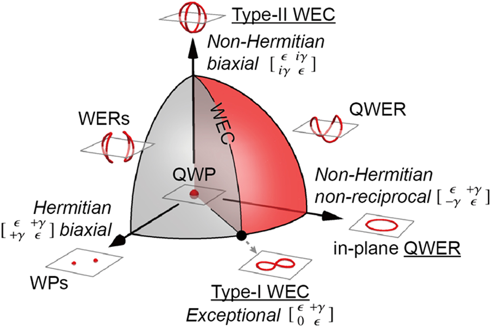
Fig. 1. Unconventional Weyl exceptional contours in non-Hermitian anisotropic chiral plasma, parameterized by the in-plane permittivity. When the contour splits or not, the space is divided into the red part, the gray part, and the boundary in between, corresponding to the QWERs, two separated WERs, and the WECs. Underlined are three special cases that pinned in planes by pseudo-PT symmetries: in-plane QWERs, type I WECs with a single chain point, and type II WECs with two chain points.
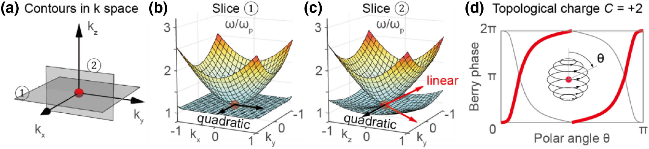
Fig. 2. Quadratic Weyl point in Hermitian anisotropic chiral plasma. (a) Isofrequency contour at the plasma frequency in the k k = 0 χ < 0 + 4 π C = + 2
Fig. 3. Four typical cases evolving from the QWP. (a) Two WPs, where ε ‖ = [ 1 , 0.4 ; 0.4 , 1 ] ε ‖ = [ 1 , 0.4 ; − 0.4 , 1 ] ε ‖ = [ 1 , 0.4 i ; 0.4 i , 1 ] ε ‖ = [ 1 , 0.4 ; 0 , 1 ]
Fig. 4. Metamaterial designs to implement various unconventional Weyl exceptional contours. (a) Unit cell of metamaterial. The metallic structure (in gray) is designed to create in-plane resonance to introduce chirality. By switching the in-plane permittivity of the background material to [ 4.0 , 0.5 ; − 0.5 , 4.0 ] [ 4.0 , 0.5 i ; 0.5 i , 4.0 ] [ 4.0 , 0.5 ; − 0.06 , 4.0 ] Γ k α = 0 C 2 α T α = x , y , z k x k y π / p x π / p y Γ
Fig. 5. Evolution of Berry phases on the latitude circles of the spheres enclosing (a) QWP, (b) QWER, (c) type II WEC, and (d) type I WEC. As the polar angle varies from 0 to π C = + 2
Fig. 6. k y Γ
|
Table 1. Variants of QWP When Introducing Perturbations to the In-Plane Permittivity, Where ε γ a

Set citation alerts for the article
Please enter your email address
© Copyright 2018-2021 | Chinese Laser Press. All Rights Reserved 沪ICP备15018463号-20