
Chaudry Sajed Saraj, Subhash C. Singh, Gopal Verma, Rahul A Rajan, Wei Li, Chunlei Guo. Laser-induced periodic surface structured electrodes with 45% energy saving in electrochemical fuel generation through field localization[J]. Opto-Electronic Advances, 2022, 5(11): 210105
- Opto-Electronic Advances
- Vol. 5, Issue 11, 210105 (2022)
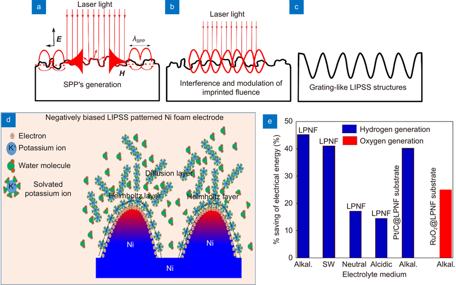
Fig. 1. Schematic illustrations of LIPSS formation, localized electric field induced enhancement in reagent concentration and experimental results of decrease in electrical energy . Schematic of LIPSS formation (a ) surface plasmon polariton (SPP) generation and propagation parallel to the surface, (b ) interference between the incident light wave and SPP wave to modulate the light intensity, and (c ) imprinting of the interference pattern through selective ablation of material. (d ) Schematic of the Gouy-Chapman-Stern electrical double layer model to represent mechanism behind localized electric field induced enhancement in the reagent concentration, and (e ) experimental results showing percentage decrease in the required electrical potential to generate 10 mA/cm2 of current density using the LIPSS patterned electrodes in different electrolytes (i.e., alkaline, seawater (SW) neutral, acidic solutions).
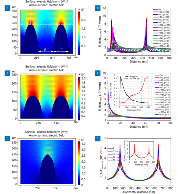
Fig. 2. Finite Element Model (FEM) simulation for the spatial distribution of the electric fields around the ridges and grooves of –1 V biased LIPSS patterns . Electric field mapping without considering nanoparticles on the ridges and grooves with geometric parameters (a ) g:180 nm, r:150 nm, and h: 240 nm, and (b ) g: 100 nm, r: 240 nm and h: 125 nm, and (c ) with the addition of 5 nm nanoparticles at the ridge. Electric field intensity along the (d ) horizontal and (e ) vertical dotted lines, shown in (a), for LIPSSs patterns of different geometric parameters without nanoparticles, inset of (e) showing the variation in the electric field intensity with respect to dimension of ridges and groove. (f ) Spatial variation in the electric field intensity along the horizontal dotted line for the LIPSS pattern shown in (a) with the addition of spherical nanoparticles of different sizes.
Fig. 3. The surface morphology and topography of LIPSS patterned electrodes . The SEM images of LIPSS patterned Ni foam (LPNF) electrode using (a ) 236, (b ) 460, (c ) 600, and (d )700 μJ/pulse of femtosecond laser pulse energy having 1 kHz repetition rate. The focused laser beam was scanned on the Ni foam target with the scanning speed of 1 mm/s.
Fig. 4. Demonstration of LEFIRC effect induced reduction in the overpotential for electrochemical hydrogen generation when the LIPSS patterned electrode is directly used as electrocatalyst . HER performance of BNF and different LPNF electrodes with Pt/C electrode as a reference in 1.0 M KOH solution at room temperature: (a ) the LSV curves and corresponding, (b ) Tafel slopes, and (c ) Nyquist plots. (d ) The LSV curves before (solid black) and after (dotted red) 2000 CV cycles. (e ) The FEM simulation for the distribution of electric field intensity along the horizontal line for the different LIPSS patterns without considering the effects of nanoparticles. (f ) Comparison of electric field localization at the ridges of LPNF- 600 and LPNF-700 electrodes with the addition of NPs of average sizes 15 nm, and 40 nm respectively. Inset (corresponding 2D mapping of electric field localization).
Fig. 5. LSV curves and chronopotentiometry (CP) test for BNF and LPNF sample in (a ) seawater solution, (b ) CP test in seawater, (c ) 0.5 M H2SO4, and (d ) deionized water.
Fig. 6. Demonstration of LEFIRC effect induced reduction in the electrochemical fuel generation potential when the LPNF-600 sample is used as a cathode or an anode substrate to support Pt/C or RuO2 electrocatalyst . (a –d ) HER and (e –h ) OER measurements for Pt/C and RuO2 inks loaded on BNF and LPNF-600 substrates in 1.0 M KOH solution at room temperature.
Fig. 7. Demonstration of LEFIRC effect induced reduction in the overall water splitting potential when the LIPSS patterned electrodes are used as an anode and a cathode . (a , b ) The LPNF surfaces are directly used as electrocatalysts for an anode and a cathode (a) the LSV curves for overall water splitting from different combinations of LPNF and BNF electrodes, and (b) corresponding chronopotentiometry Chronopotentiometrycurves for 24 hours. (c , d ) A pair of LPNF-600 surfaces are used as substrates to support Pt/C and RuO2 electrocatalysts to make cathode and anode, respectively of the cell along with a similar cell made with the BNF substrates for comparison (c) the LSV curves for overall water splitting and (d) corresponding chronopotentiometry curves for 24 hours.
Fig. 8. (a ) X-ray photoelectron spectra (XPS). (b ) SEM images. (c ) ECSA normalized atomic concentration of K+ ions at the surface of –1 V (vs. RHE) biased LPNF electrodes in 1.0 M KOH solution.

Set citation alerts for the article
Please enter your email address
© Copyright 2018-2021 | Chinese Laser Press. All Rights Reserved 沪ICP备15018463号-20