Chaudry Sajed Saraj, Subhash C. Singh*, Gopal Verma, Rahul A Rajan..., Wei Li** and Chunlei Guo***|Show fewer author(s)
Abstract
Electrochemical oxidation/reduction of radicals is a green and environmentally friendly approach to generating fuels. These reactions, however, suffer from sluggish kinetics due to a low local concentration of radicals around the electrocatalyst. A large applied electrode potential can enhance the fuel generation efficiency via enhancing the radical concentration around the electrocatalyst sites, but this comes at the cost of electricity. Here, we report about a ~45% saving in energy to achieve an electrochemical hydrogen generation rate of 3×10¹⁶molecules cm–2s–1 (current density: 10 mA/cm2) through localized electric field-induced enhancement in the reagent concentration (LEFIRC) at laser-induced periodic surface structured (LIPSS) electrodes. The finite element model is used to simulate the spatial distribution of the electric field to understand the effects of LIPSS geometric parameters in field localization. When the LIPSS patterned electrodes are used as substrates to support Pt/C and RuO2electrocatalysts, the η10 overpotentials for HER and OER are decreased by 40.4 and 25%, respectively. Moreover, the capability of the LIPSS-patterned electrodes to operate at significantly reduced energy is also demonstrated in a range of electrolytes, including alkaline, acidic, neutral, and seawater. Importantly, when two LIPSS patterned electrodes were assembled as the anode and cathode into a cell, it requires 330 mVs of lower electric potential with enhanced stability over a similar cell made of pristine electrodes to drive a current density of 10 mA/cm2. This work demonstrates a physical and versatile approach of electrode surface patterning to boost electrocatalytic fuel generation performance and can be applied to any metal and semiconductor catalysts for a range of electrochemical reactions.Electrochemical oxidation/reduction of radicals is a green and environmentally friendly approach to generating fuels. These reactions, however, suffer from sluggish kinetics due to a low local concentration of radicals around the electrocatalyst. A large applied electrode potential can enhance the fuel generation efficiency via enhancing the radical concentration around the electrocatalyst sites, but this comes at the cost of electricity. Here, we report about a ~45% saving in energy to achieve an electrochemical hydrogen generation rate of 3×10¹⁶molecules cm–2s–1 (current density: 10 mA/cm2) through localized electric field-induced enhancement in the reagent concentration (LEFIRC) at laser-induced periodic surface structured (LIPSS) electrodes. The finite element model is used to simulate the spatial distribution of the electric field to understand the effects of LIPSS geometric parameters in field localization. When the LIPSS patterned electrodes are used as substrates to support Pt/C and RuO2electrocatalysts, the η10 overpotentials for HER and OER are decreased by 40.4 and 25%, respectively. Moreover, the capability of the LIPSS-patterned electrodes to operate at significantly reduced energy is also demonstrated in a range of electrolytes, including alkaline, acidic, neutral, and seawater. Importantly, when two LIPSS patterned electrodes were assembled as the anode and cathode into a cell, it requires 330 mVs of lower electric potential with enhanced stability over a similar cell made of pristine electrodes to drive a current density of 10 mA/cm2. This work demonstrates a physical and versatile approach of electrode surface patterning to boost electrocatalytic fuel generation performance and can be applied to any metal and semiconductor catalysts for a range of electrochemical reactions.Introduction
The incessantly growing global energy demands and greenhouse gas emissions pose enormous pressure on developed and developing countries to urgently replace their fossil-fuel-based conventional energy sources with renewable ones that have zero or negative carbon emissions1,
2. Electrochemical (EC) and photoelectrochemical (PEC) oxidation/reduction of radicals at electrodes are green, environmentally friendly, and sustainable approaches and are currently used in the generation of hydrogen, oxygen, ammonia, hydrocarbons, and other fuels3-
6. These oxidation/reduction reactions, however, suffer from sluggish kinetics owing to the low local concentration of radicals close to the electrode surface. The concentration of radicals (i.e. K+, H+, OH– ions) and bond activation, thus the rate of fuel generation, can be increased via the application of a large external electric potential, but this comes at the cost of consumed electricity7,
8. An enormous amount of effort has been devoted to designing and producing EC or PEC catalysts that could efficiently operate near-zero or at a low electric potential to develop self or atmospheric energy-powered fuel cells9-
14. Most of these efforts, however, were centered on lowering the activation energy barrier i.e., thermodynamics of catalysts either via edge site engineering through nanostructuring15-
21 or enhancing the intrinsic activity of edge sites through chemical doping22-
26. Little work has been done in modulating local electric fields surrounding the catalysts that can directly govern the local concentration of radicals to enhance the kinetics of the reactions.
Recently, some efforts have been made to computationally optimize and experimentally realize the roles of long-range electric fields at the electrode-electrolyte interfaces or at the active sites to boost the biocatalytic performance of enzymes27,
28. Sargent et al. demonstrated an enhancement in electrocatalytic CO2 reduction performance by modulating reagent concentration via electric field localization at gold tip electrodes, which shows that optimization of kinetics can be one of the most important efficient ways to design high-performance electrocatalysts29. Orientation of external electric fields at the surface of a catalyst can be used to catalyze and control several non-redox, even nonpolar, reactions by several orders of magnitudes, and to tune catalytic selectivity30-
33. Very recently, Yu et al. demonstrated that the catalysts with ordered nanostructures are even better to regulate the surface flux of the reactant molecules for their proper utilization in the chemical reactions resulting in ~ 2 times higher current density34, which strongly indicates that the design and optimization of periodic surface patterns on catalysts surface can be one of the most efficient ways to realize next-generation smart catalysts.
In general, the fabrication of periodic nanopatterns on a metal surface relies either on multi-step, tedious, and time-consuming lithography-based selective etching/deposition techniques or self-assembling routes35,
36. Recently, it is demonstrated that femtosecond laser can create high-quality periodic patterns with sub-micron resolution, creating the so-called laser-induced periodic surface structures (LIPSSs). In contrast to complex lithography methods, LIPSSs can be produced in an ambient environment on a flat or curved surface of any materials such as metals, semiconductors, and dielectrics using a single step, faster, and mask less approach37-
40. Surprisingly, LIPSSs have never been used for electric field localization to boost electrochemical fuel generation performance until this work.
Here, we fabricate LIPSSs on Ni foam (NF), one of the widely used electrode materials, and control geometric parameters to optimize localized electric field-induced modulation in the reagent concentration (LEFIRC) at the electrode surface. The LIPSSs patterned electrodes have hierarchical structures with periodic ridges and grooves of 100–300 nm widths covered with spherical nanoparticles (NPs) of 3–94 nm in diameters. The LEFIRC effect which boosts the electrochemical fuel generation performance is tested for electrochemical hydrogen and oxygen generations through hydrogen evolution reaction (HER) and oxygen evolution reaction (OER), respectively. The optimized LIPSS patterned electrode demonstrates about a ~45% reduction in the required electrical energy to achieve a hydrogen generation rate of 3×10¹⁶ molecules cm–2 s–1 (at current density: 10 mA/cm2). Furthermore, the applicability of the LIPSS patterned electrodes as a substrate to support and boost the performance of electrocatalyst powders through the LEFIRC effect is also examined. The Pt/C, the model HER electrocatalyst, loaded on the LIPSS patterned NF substrate, demonstrated ~130 mV (40.4%) of lower η10 overpotentials in the HER over the same loading of electrocatalysts on the pristine NF electrode along with significantly improved stability. Similarly, RuO2 electrocatalyst powder, the model OER electrocatalyst, loaded on the LIPSS patterned NF substrate, required ~100 mV (25%) lower η10 overpotentials in the OER with significantly enhanced stability. Importantly, when two LIPSS patterned electrodes were assembled simultaneously as anode and cathode to make a cell, it requires 330 mV of lower electric potential over a similar cell made of pristine NF electrodes to drive 10 mA/cm2 in overall water. The capability of the LIPSS patterned electrodes to operate at significantly reduced electric potentials is demonstrated in a range of electrolytes, including alkaline, acidic, neutral, and seawater. The present work demonstrates a single-step, fast, and physical approach of electrode surface patterning to boost electrocatalytic fuel generation performance and can be applied to any metal and semiconductor catalysts for reducing the required electrical power in a range of electrochemical reactions.
Experimental section
COMSOL multiphysics simulations
To calculate the electric field generated by our LIPSS patterned on Ni foam (LPNF) electrodes, we used Finite Element-based solver COMSOL Multiphysics. The Electrostatics module was used to compute the electric (E = –
) under a specific electrode bias potential. Two-dimensional geometry was built to represent the nanorod and nanoparticle structures in this work. Triangular meshes were used for all simulations. Meshes were set to be the densest at the surface of the electrodes.
Materials
Ni foam (thickness 1.5 mm, porosity ~98%) was purchased from Sigma-Aldrich. All chemicals including potassium hydroxide (KOH) were purchased from Aladdin Co., Ltd., and used without further purification. Deionized (DI) water (resistivity ≥ 18.3 MΩ) was used as the medium for the preparation of an aqueous electrolyte solution.
Fabrication of laser-induced periodic surface structures (LIPSS) on Ni foam
The fabrication of LIPSS on bare Ni foam (BNF) was performed with the laser at 800 nm, 40 fs pulses from Ti: Sapphire laser (Spitfire Ace, Spectra-Physics) at a 1 kHz repetition rate. The maximum pulse energy output from the laser system is 6 mJ, which was attenuated using the combination of a half-wave plate and a linear polarizer. The fast fabrication of LIPSS on the surface of 0.5 cm × 0.5 cm nickel foam samples could do with the cylindrical lens of 75 mm focal length and an XYZ translational stage. Samples were scanned across the optical axis by fixing at the computer-controlled translational stage. Provided, the laser beam was irradiated on the surface at normal incidence. The fabrication was carried out with 95 µJ, 236 µJ, 460 µJ, 600 µJ, and 700 µJ pulse energy and 1 mm/s scanning speed at the focal point. For convenience, the so-fabricated LIPSS on Ni foam is abridged as LPNF-95, LPNF-236, LPNF-460, LPNF-600, and LPNF-700.
Synthesis of Pt/C and RuO2 electrodes @NF and LPNF
To prepare the electrocatalyst inks, commercial Pt/C 20% or RuO2 (5 mg) catalysts powder was dispersed in 1 mL of ethanol and DI water (V=1:1) mixture. The ink of each catalyst was prepared by first ultrasonication of the solution for 1 h, then by adding 36 μL Nafion solution into the mixture as adhesive. To make a homogeneous suspension, the final mixture was ultrasonicated for 30 min. Then the prepared slurry was painted onto the BNF and LPNF-600 substrates and finally dried at room temperature. For our simplicity, the as-synthesized electrocatalysts are abbreviated as Pt@BNF, Pt@LPNF-600, RuO2@BNF, and RuO2@LPNF-600.
Characterization of LPNF electrocatalysts
The X-ray diffraction (XRD) measurements of different samples were carried out using Bruker D8 Focus X-ray diffractometer with Cu-Kα (λ= 1.5406 Å, 1 Å=10–10 m) radiation operating at a voltage of 40 kV and a current of 30 mA. Morphological and elemental information of the as-prepared electrocatalysts were characterized by field emission scanning electron microscopy (SEM, HITACHI S4800) equipped with an energy-dispersive X-ray spectroscopy (EDS) analyzer. The X-ray photoelectron spectroscopy (XPS) was performed on a Thermo ESCALAB 250Xi using Al Kα as the excitation X-ray source.
Electrochemical measurements
The electrochemical measurements were performed on a BioLogic VMP3 multichannel workstation with a three-electrode system, where a Pt wire, fabricated LPNF electrocatalysts (0.5 cm × 0.5 cm), and a saturated calomel electrode (SCE) were used as a counter, working and reference electrodes, respectively. An aqueous solution of 1.0 M KOH was used as an electrolyte for the electrochemical measurements. Each of the working electrodes was pre-scanned for 50 Cycles of cyclic voltammetry (CV) with the scan rate of 40 mVs–1 before performing linear sweep voltammetry (LSV) curves. The LSV curves were measured by sweeping voltage in the range of –0.2 to –1.6 V vs. SCE electrode with the scan rate of 10 mVs–1. The expression
, where
, was used to translate V vs. SCE to V versus reverse hydrogen electrode (RHE)41. Electrochemical impedance spectroscopy (EIS) was measured at a DC overpotential of 0.341 V vs. RHE (For HER), superimposing a small alternating voltage of 10 mV over the frequency range of 10 mHz to 1 MHz. The CV curves were further measured in the non-Faradaic region of potential from 0.84 V to 1.04 V (versus RHE) for HER with different scan rates (from 20 mVs–1 to 120 mVs–1 for HER, to estimate the double-layer capacitance (Cdl) and electrochemically active surface area (ECSA). The slope of the difference in the cathodic and anodic current densities (
) with the scan rate resulted in Cdl. The ECSA values were then calculated using the expression
(per ECSA) cm−2; where, Cdl(NF) is the double layer capacitance for the bare Ni foam42. Here, we used the Cdl value of the bare Ni foam instead of the general specific capacitance (Cs) to exclude the effect of the larger capacitance value of bare NF. All the electrochemical measurements were performed at room temperature. The long-term durability measurements were done using chronopotentiometry (CP) for 24 hours and 2000 CV cycling at fast scan. The LSV test was performed before and after the durability measurements.
Results and discussion
Schematic illustration and experimental setup for the femtosecond laser writing of LIPSSs on a Ni foam electrode are shown in
Fig. 1(a–c) and
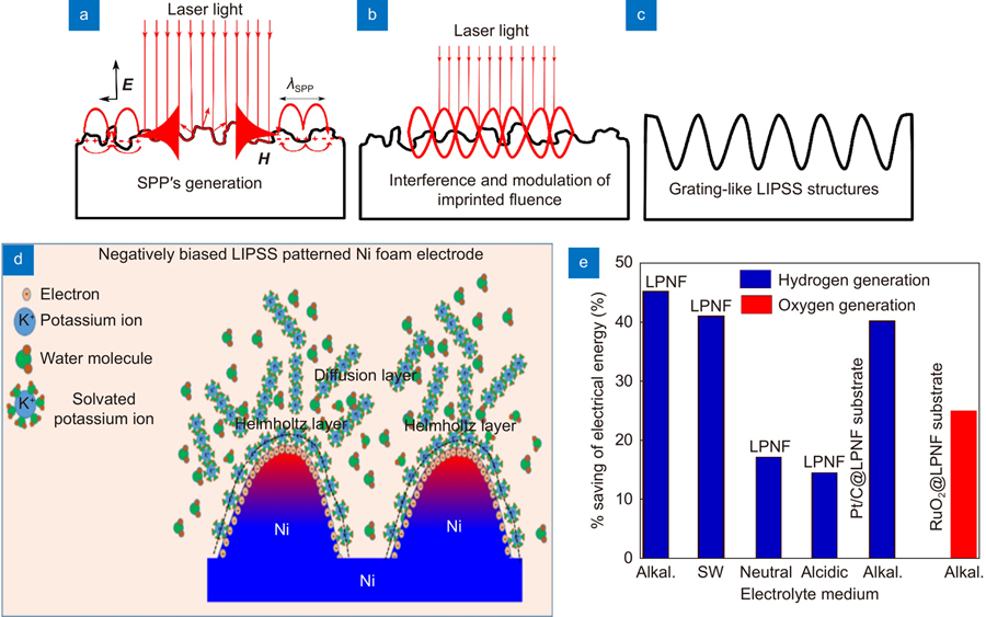
Fig. S1, respectively. In a typical LIPSS experiment, a burst of linearly polarized femtosecond laser pulses is focused on the target surface. Depending on the instantaneous surface roughness, a fraction of absorbed radiation excites surface plasmon polaritons (SPPs) wave on the sample surface (
Fig. 1(a)), while the rest of the absorbed energy gets transferred to the lattice through electron-phonon interaction. According to electromagnetic theory, interference between the incident radiation with the SPPs results in spatial modulation of the intensity at the target surface43,
44 (
Fig. 1(b)). Finally, the interference pattern gets imprinted through selective ablation of the material to form LIPSSs (
Fig. 1(c)). The formation of LIPSSs is a sequential phenomenon where the structures formed via a preceding laser pulse guides the structures to be formed with the next laser pulse. Therefore, for given pulse width, the geometric parameter of a LIPSS pattern depends on the number of pulses at a given place and the laser pulse energy. We fabricated five different LIPSSs patterned nickel foam (LPNF) electrodes using 95, 236, 460, 600, and 700 µJ/pulse laser energy and 1 mm/s scanning speed. Hereafter, the LIPSSs patterned electrocatalysts are referred as LPNF-95, LPNF-236, LPNF-460, LPNF-600, and LPNF-700, respectively while the bare NF electrode is presented as BNF. When a LIPSSs patterned electrode will be placed in an alkaline medium it would form an electrostatic arrangement at the electrode-electrolyte interface and in the electrolyte. A schematic of the Gouy-Chapman-Stern electrical double layer with Helmholtz and diffusion layers is shown in
Fig. 1(d) and
Fig. S2.

Figure 1.Schematic illustrations of LIPSS formation, localized electric field induced enhancement in reagent concentration and experimental results of decrease in electrical energy. Schematic of LIPSS formation (a) surface plasmon polariton (SPP) generation and propagation parallel to the surface, (b) interference between the incident light wave and SPP wave to modulate the light intensity, and (c) imprinting of the interference pattern through selective ablation of material. (d) Schematic of the Gouy-Chapman-Stern electrical double layer model to represent mechanism behind localized electric field induced enhancement in the reagent concentration, and (e) experimental results showing percentage decrease in the required electrical potential to generate 10 mA/cm2 of current density using the LIPSS patterned electrodes in different electrolytes (i.e., alkaline, seawater (SW) neutral, acidic solutions).
The Helmholtz layer consists of a monolayer of surface adsorbed solvated cations on the nanostructured electrode surface while the diffusion layer consists of cations and anions that diffuse freely in the electrolyte and forms a concentration gradient29. Localization of electric field near the curved surfaces of a biased electrode forms hotspots. These hotspots can pull water molecules, adsorbed on the cations’ surfaces (
Fig. 1(d)) and
Fig. S2), from the bulk of the electrolyte to their surfaces to dissociate them at much lower applied electric potential to produce H+ and OH– reagents for hydrogen and oxygen generations, respectively. The intensity of the hotspots depends on the geometric parameters of the LIPSSs pattern, and the size and density of NPs present at the surface.
Fig. 1(e) shows a histogram summarizing results of percentage decrease in the required electrical energy to drive 10 mA/cm2 current density in different electrolytes for hydrogen (blue bars) and oxygen (red bars) generations.
First, we used the FEM simulation to explore the interconnection between the surface topography (dimensions of ridges and grooves) and morphology (size and density of NPs) of the LIPSSs patterns and intensity of the hotspots. A semi-elliptical periodic structure with a ridge width r and a groove width g is used to represent the cross-section of a LIPSS patterned electrode. The electric field mappings around negatively biased LIPSSs patterned electrodes with geometric parameters; g: 180 nm, r: 150 nm, and h: 240 nm (
Fig. 2(a)) and g: 100 nm, r: 240 nm, and h: 125 nm (
Fig. 2(b)) are shown in
Fig. 2. Because of the electrostatic repulsion, the free electrons in the negatively biased electrode get migrated to the region of high curvature (near the tip) resulting in the generation of a highly localized electrostatic field. The localized electric field intensity for the LIPSSs patterns with the radii of ridge curvatures 120 nm (
Fig. 2(a)) and 135 nm (
Fig. 2(b)) are ~2.5×10⁷ and 2.0×10⁷ V/cm respectively. The spatial variations in the horizontal and vertical components of the electric fields for different LIPSSs’ parameters are demonstrated in
Fig. 2(d) and
2(e), respectively. Compared to the flat surface (E-field; 1.7×10⁷), the LIPSS patterned electrode with r= 10 nm (E-field; 9.5×10⁷) can generate ~ 5.58 times intense hotspots. Moreover, NPs on the surface of ridges and grooves can further enhance the intensity of hotspots (
Fig. 2(c)). To understand the effects of the size of NPs and their density on the E-field localization, we performed extensive simulation (see Supplementary information
Figs. S3– S6). We chose g: 180 nm, r: 150 nm, and h: 240 nm periodic structure of Ni, shown in
Fig. 2(b), and put spherical Ni NPs on the ridges. The presence of Ni NPs of 5 nm diameter on the ridges shows enhancement in the E-field intensity from 2.5×10⁷ to 4.5×10⁷ V/cm (
Fig. 2(a) versus
Fig. 2(c); see
Fig. S4(a) and
S4(b)).
Fig. 2(f) shows the spatial distribution of the horizontal component of the E-field for the bare LIPSSs (shown in
Fig. 2(a)) and the same LIPSSs decorated with Ni NPs of different diameters. The presence of NPs of 5 and 10 nm diameters localizes the E-field strongly as compared to NPs of larger diameters. For example, the NPs of 50 nm diameter have a negligible effect on the enhancement of E-field intensity.
Figure 2.Finite Element Model (FEM) simulation for the spatial distribution of the electric fields around the ridges and grooves of –1 V biased LIPSS patterns. Electric field mapping without considering nanoparticles on the ridges and grooves with geometric parameters (a) g:180 nm, r:150 nm, and h: 240 nm, and (b) g: 100 nm, r: 240 nm and h: 125 nm, and (c) with the addition of 5 nm nanoparticles at the ridge. Electric field intensity along the (d) horizontal and (e) vertical dotted lines, shown in (a), for LIPSSs patterns of different geometric parameters without nanoparticles, inset of (e) showing the variation in the electric field intensity with respect to dimension of ridges and groove. (f) Spatial variation in the electric field intensity along the horizontal dotted line for the LIPSS pattern shown in (a) with the addition of spherical nanoparticles of different sizes.
The scanning electron microscopy (SEM) images (
Fig. 3) of the LIPSSs patterned NF electrodes can be used to extract the average dimensions of ridges and grooves and the size of the NPs on their surfaces. At a low laser pulse energy (236 μJ/pulse), the LIPSSs pattern is irregular and short length (
Fig. 3(a) middle panel) with 60 and 100 nm average dimensions of ridges and grooves, respectively, with very low density of NPs. With an increase in the laser pulse energy, up to 600 μJ/pulse, the ratio of groove to ridge (g/r) widths increases (see Supporting information
Table S1) with an increase in the regularity of the LIPSSs pattern and lengths of the ridges and grooves (See
Fig. 3(b) and
Fig. 3(c); left panels). For example, the length and regularity of the LIPSSs pattern at LPNF-460 (
Fig. 3(b); left panel) is certainly higher as compared to the LIPSSs pattern at the LPNF-236 electrode (
Fig. 3(a); left panel), but lower than the pattern formed at the LPNF-600 electrode (
Fig. 3(c); left panel). From these images, we can see that the depth of the grooves and density of NPs on the surface of the LIPSSs are larger at higher laser pulse energies (see
Table S1). The LIPSSs pattern at the LPNF-600 electrode has 240 nm average sizes of grooves and ridges where the surface is covered with spherical NPs of 16.6±8.4 nm average diameter (see Supporting information
Fig. S7). Further increase in the laser pulse energy to 700 μJ/pulse possibly results in the melting of smaller sized NPs and solidification of the melted material on the sides of ridges, consequently formation of wider rides (270 nm), narrower (130 nm) grooves, and larger size of NPs at the surface. The surface of the LPNF-700 electrode has hemispherical NPs with an average diameter of 39.2±3.2 nm (see Supplementary information
Fig. S7). The X-ray diffraction spectra of the LPNF-600 and BNF electrodes show that the surface chemistry of the electrodes is retained after laser surface treatment (see Supplementary information
Fig. S8).
Figure 3.The surface morphology and topography of LIPSS patterned electrodes. The SEM images of LIPSS patterned Ni foam (LPNF) electrode using (a) 236, (b) 460, (c) 600, and (d)700 μJ/pulse of femtosecond laser pulse energy having 1 kHz repetition rate. The focused laser beam was scanned on the Ni foam target with the scanning speed of 1 mm/s.
To verify the proposed LEFIRC effect induced enhancement in the electrochemical fuel generation performance, we first tested the HER activity of the as-fabricated LIPSSs patterned electrodes in an alkaline (1.0 M KOH) medium and later in other electrolytes.
Fig. 4(a) shows the linear sweep voltammetry (LSV) curves, with iR compensation, for different LIPSSs patterned NF and BNF electrodes along with the LSV curve of a Pt-rod electrode for reference (see non-iR compensated LSV curvesin Supplementary information
Fig. S10). At a given applied potential, the current density increases with an increase in the groove to the ridge ratio (g/r) of the LIPSSs patterned electrode and has a maximum current density value for the LPNF-600 electrocatalyst having the highest g/r value (see Supplementary information
Table S2 and
Table S3). The LPNF-700 electrocatalyst shows comparatively lower current density due to a decrease in the electric field intensity from wider ridges, narrower grooves, and larger sizes of NPs on the LIPSSs surface (see Supplementary information
Fig. S7 and
Table S1). From the LSV curves, we can see that LPNF-600 is the best HER performer with the highest current density at a given overpotential. The origin of enhanced current density, at a given potential, can be a combination of increased electrochemical surface area (ECSA) and the LEFIRC effect. The LIPSS patterning can alter the ECSA value of the electrode thus corresponding current density. To evaluate the contribution of the LEFIRC effect and ECSA on the enhanced current density, we calculated ECSA values of the LIPSSs patterned electrodes using the corresponding double-layer capacitance (Cdl) values extracted from corresponding cyclic voltammetry (CV) curves recorded at different scan rates in non-Faradaic regions (see Supplementary information
Figs. S11–S13 and
Table S4). The ECSA value for the LPNF-95 electrocatalysts sample (0.81) is relatively lower than the BNF (1.0) electrocatalyst indicating that the fs laser pulses remove pre-existing surface textures at the NF and made it relatively smoother with ultrafine periodic patterns (see Supplementary information
Fig. S15). In contrast, at higher laser pulse energies, the ECSA value of the LIPSSs patterned electrodes increases with an increase in the laser power resulting in 1.44 and 2.19 values for the LPNF-600 and LPNF-700 electrodes, respectively.
Figure 4.Demonstration of LEFIRC effect induced reduction in the overpotential for electrochemical hydrogen generation when the LIPSS patterned electrode is directly used as electrocatalyst. HER performance of BNF and different LPNF electrodes with Pt/C electrode as a reference in 1.0 M KOH solution at room temperature: (a) the LSV curves and corresponding, (b) Tafel slopes, and (c) Nyquist plots. (d) The LSV curves before (solid black) and after (dotted red) 2000 CV cycles. (e) The FEM simulation for the distribution of electric field intensity along the horizontal line for the different LIPSS patterns without considering the effects of nanoparticles. (f) Comparison of electric field localization at the ridges of LPNF- 600 and LPNF-700 electrodes with the addition of NPs of average sizes 15 nm, and 40 nm respectively. Inset (corresponding 2D mapping of electric field localization).
To explore the LEFIRC’s contribution in the electrocatalytic performance of the LIPSSs patterned electrodes, we normalized the LSV curves with corresponding ECSA values (see Supplementary information
Fig. S14 (c, d)). Comparing the η10 overpotential values between the original (
Fig. S14(b)) and corresponding ECSA normalized LSV curves (
Fig. S14(d)), we estimated that the ECSA contribution is almost negligible in the LPNF-95, LPNF-236, and LPNF-460 LIPSSs patterned electrodes and have about 3% and 12% contributions in the LPNF-600 and LPNF-700 electrodes, respectively. From the detailed investigations, we can claim that the LEFIRC effect is the main cause of higher observed electrocatalytic hydrogen generation performance in all the LIPSSs patterned electrodes. The LEFIRC effect at the LIPSS patterned electrodes reduces η10 overpotential values in the range of 13 to ~43%. The LIPSSs patterns at the LPNF-600 electrode reduces the required electrical energy by ~ 45% to achieve a hydrogen generation rate of ~3×10¹⁶ molecules cm–2 s–1 (at current density: 10 mA/cm2) via the synergistic effects of LEFIRC and ECSA enhancements where ~ 42.4% contribution is purely from the LEFIRC effect (see Supplementary information).
As shown in
Fig. 4(b), the Tafel slopes for the BNF, LPNF-95, LPNF-236, LPNF-460, LPNF-600, and LPNF-700 electrocatalyst electrodes are 118, 109, 110, 87, 63, and 78 mV/dec, respectively (see Supplementary information
Table S2 and
Table S3). The Tafel slope for the most efficient LIPSS patterned electrode, LPNF-600, is 46.6% lower as compared to the BNF. The electrochemical impedance spectroscopy (EIS) (
Fig. 4(c)) of the electrocatalyst samples shows that the LPNF-600 (2.5 Ω) electrocatalyst has significantly lower charge-transfer resistance as compared to the LPNF-700 (2.6 Ω), LPNF-460 (5.3 Ω), LPNF-236 (6.8 Ω), LPNF-95 (7.8 Ω), and the bare NF (11.4 Ω) electrocatalysts resulting in a higher rate of electron transfer from the catalyst to reduce the adsorbed H* in the Volmer step of the HER. The localization of the electric field of the order of ~4.0×10⁷ V/cm can increase the concentration of H* radicals on the catalyst surface through the electrostatic attraction of the solvated potassium ions and dissociation of water molecules adsorbed on their surface (
Fig. 1(f) and
Fig. S2). Moreover, the long-term durability of an electrocatalyst is an important parameter to evaluate its performance. A complete overlap of the LSV curve recorded after 2000 CV cycles (
Fig. 4(d)) with the initial one demonstrates excellent stability of the LPNF-600 electrocatalyst cathode in an alkaline medium. The LSV curves before and after 2000 CV cycles for the LPNF-460 and LPNF-700 electrocatalyst samples demonstrate their excellent stability in the alkaline medium (
Fig. S15). To understand the reason behind the higher electrochemical performance of the LPNF-600 electrocatalyst over others, we extracted geometric parameters of the LIPSS patterns for each sample and measured the size of nanoparticles at ridges and grooves from corresponding SEM images. These data are used to calculate the electric field profiles (see Supplementary information
Fig. S9) for each sample (
Fig. 4(e)). The trend of the calculated electric field intensity supports the observed trend in the electrochemical performance. Moreover, the smaller size of nanoparticles (av: 16.6±8.4 nm) at the surface of LPNF-600 electrocatalyst better localize (3.75×10⁷ V/cm) electric field, thus has a higher LEFIRC effect induced electrochemical fuel generation performance over the LPNF-700 electrocatalyst covered with 39±3.2 nm average size of particle generating 2.7×10⁷ V/cm of the electric field (
Fig. 4(f)). Where the ratio of area under the curve from LPNF-600 to LPNF-700 is 1.04 cm2 (inset;
Fig. 4(f)).
Figure 5.LSV curves and chronopotentiometry (CP) test for BNF and LPNF sample in (a) seawater solution, (b) CP test in seawater, (c) 0.5 M H2SO4, and (d) deionized water.
According to the Gouy-Chapman-Stern model, (Schematic
Fig. 1(f) and
Fig. S2) the density of water molecules that can be electrostatically transported to the electrode surface through solvation depends on the size, charge, and mobility of the carrier cation/anion of the electrolyte. For example, a cation/anion with higher valency experiences a higher electrostatic force, but the rate of transport of these ions to the electrode depends on their mobility. To explore the roles of electrolytes on the LEFIRC effect induced reduction in the required electrical power in fuel generation, we tested the HER performance of the LPNF-600 electrode in seawater (4× 10⁴ ppm NaCl), acidic (0.5 M H2SO4), and neutral (DI water 18 MΩ-cm) electrolyte media (see
Fig. 5 and Supplementary information
Figs. S16 and
S17). The η10 overpotentials for the LPNF-600 electrode in seawater, acidic, and neutral electrolytes are 335, 326, and 748 mVs those are ~ 41, 14, and 16.8% lower as compared to the corresponding overpotentials of the BNF electrode.
Periodically patterned substrates, known as metasurfaces, are widely used in plasmonics and nanophotonics to boost performances of photodetectors, photovoltaics, solar cells, and plasmonic sensors as well as in guiding and manipulating the characteristics of light45-
57. However, unfortunately periodically patterned surfaces are never used as substrates to boost the performance of electrocatalyst powders. To extend the application of the LIPSSs patterned electrode as a substrate that not only can support a powder electrocatalyst or ink but can also enhance its performance via the LEFIRC effect, we selected the LPNF-600 electrode and loaded it with Pt/C or RuO2 (
Fig. 6) powder electrocatalyst to enhance their HER or OER performances, respectively in an alkaline solution. The LSV curves for the BNF and LPNF-600 electrodes, loaded with 0.25 mg/cm2 of Pt/C (ratio; 2:8) electrocatalysts powder, show 302 and 180 mVs of η10 overpotentials, respectively resulting in ~40.4% decrease in the required electrical power (
Fig. 6(a) and
Fig. S18) to drive 10 mA/cm2 of current density. At an applied electric potential of 558 mV, the hydrogen generation performance of the LPNF-600 substrate is enhanced by 270% over the BNF substrate. The corresponding Tafel slope for the LPNF-600 substrate (128 mV/dec) is 11.7% smaller as compared to the BNF substrate (145 mV/dec) (
Fig. 6(b)). The enhanced performance of the LPNF-600 substrate is also evidenced by a decrease in its charge transfer resistance to a small value of 2.25 Ω as compared to > 1 kΩ resistance for the BNF substrate (
Fig. 6(c) and
Fig. S19). The chronopotentiometry curves, at 10 mA/cm2 current density, for the LPNF-600 and BNF substrates (
Fig. 6(d)) further show long-term stability of the LIPSS patterned substrate in the E-filed localization.
Figure 6.Demonstration of LEFIRC effect induced reduction in the electrochemical fuel generation potential when the LPNF-600 sample is used as a cathode or an anode substrate to support Pt/C or RuO2 electrocatalyst. (a–d) HER and (e–h) OER measurements for Pt/C and RuO2 inks loaded on BNF and LPNF-600 substrates in 1.0 M KOH solution at room temperature.
In the previous sections, we presented the capability of the LIPSS patterned electrodes as a cathodes to demonstrate the LEFIRC effect-induced reduction in the electrochemical fuel generation potential. Similarly, we present the performance of the LIPSSs patterned NF substrate, as an anode, to support and boost the activity of an OER electrocatalyst in an alkaline electrolyte (
Fig. 6(e–h)). The LSV curves for the BNF and LPNF-600 substrates, loaded with 0.25 mg/cm2 of RuO2 electrocatalysts powder, demonstrate that the LEFIRC effect reduces the η10 overpotentials from 400 mV (BNF) to 300 mV (LPNF-600) resulting in a 25% reduction in the required electrical power (
Fig. 6(e) and
Fig. S19(b)) to drive 10 mA/cm2 of current density. At an overpotential of 750 mV, the oxygen generation performance of the LIPSS patterned substrate is enhanced by 211% over the bare substrate (
Fig. S20(a)). The Tafel slope for the LPNF-600 substrate (78 mV/dec) is 27.1% lower as compared to the BNF (107 mV/dec) substrate (
Fig. 6(f)). The enhanced performance of the LPNF-600 substrates is also evidenced by a decrease in its charge transfer resistance to a small value of ~4 Ω as compared to > 1 kΩ resistance for the BNF electrode (
Fig. 6(g)). Moreover, the chronopotentiometry curves at 10 mA/cm2 current density for the LPNF-600 and BNF substrates (
Fig. 6(h) further demonstrates the long-term stability of the LIPSS pattern substrate in the localization of E-field and oxidation of OH– ions for oxygen generation.
Furthermore, we constructed two-electrode electrochemical cells (ECCs) using different combinations of a cathode and an anode materials for overall water splitting (
Fig. 7(a)). The electrochemical cell LPNF-600 || BNF (1.94 V) requires about 210 mV smaller electric potential to drive 10 mA/cm2 of current density as compared to the BNF || BNF cell (2.15 V). Similarly, the LPNF-600 || LPNF-600 (1.82 V), LPNF-600 || LPNF-700 (1.86 V), and LPNF-700 || LPNF-700 (1.88 V) electrochemical cells require 15.3%, 13.5%, and 12.6% lower electric potential to generate 10 mA/cm2 of current density as compared to the BNF || BNF cell (2.15 V) (
Fig. 7(a)). The chronopotentiometry curves (
Fig. 7(b)) of the ECCs made of a pair of the LIPSS patterned electrodes show that these cells can operate at significantly lower (from 160 to 270 mV) potentials for 24 hours, thus maintaining the surface patterns, morphology, and chemical composition. A two-electrode cell (Pt/@LPNF-600 || RuO2@LPNF-600) made with a pair of LPNF-600 substrates, where the first one loaded with 0.25 mg/cm2 of Pt/C (ratio; 2:8) powder serves as a cathode for the HER and another loaded with 0.25 mg/cm2 of RuO2 powder acts as an anode for the OER is tested for overall water splitting. For comparison, a similar cell (Pt/@BNF || RuO2@BNF) made with the loading of the same amount of electrocatalyst powders on the BNF substrates is also tested. It is evident from
Fig. 7(c) that the Pt/@LPNF-600 || RuO2@LPNF-600 cell operates at significantly lower potential (1.74 V) as compared to the Pt@BNF || RuO2@BNF cell (1.83 V) to drive 10 mA/cm2 of current density. The chronopotentiometry measurements of these two cells demonstrate the durability of the LIPSS patterned substrates and NPs on their surfaces against overall water splitting in an alkaline solution (
Fig. 7(d)).
Figure 7.Demonstration of LEFIRC effect induced reduction in the overall water splitting potential when the LIPSS patterned electrodes are used as an anode and a cathode. (a, b) The LPNF surfaces are directly used as electrocatalysts for an anode and a cathode (a) the LSV curves for overall water splitting from different combinations of LPNF and BNF electrodes, and (b) corresponding chronopotentiometry Chronopotentiometrycurves for 24 hours. (c, d) A pair of LPNF-600 surfaces are used as substrates to support Pt/C and RuO2 electrocatalysts to make cathode and anode, respectively of the cell along with a similar cell made with the BNF substrates for comparison (c) the LSV curves for overall water splitting and (d) corresponding chronopotentiometry curves for 24 hours.
Moreover, structural, compositional, and morphological integrities of an electrocatalyst are important parameters to ensure its long-term durability. For this purpose, we performed XPS, SEM, EDAX, and XRD measurements of the LPNF-600 sample before and after 24 hours of HER test (
Fig. 8, Supplementary information
Fig. S8 and
Figs. S20–S29). The Ni0 peaks at 852.7 and 869.9 eVs, present in the initial LPNF-600 sample (top panel of
Fig. 8(a)), disappeared after 24 hours of the HER test (bottom panel of
Fig. 8(a)) showing that surface Ni atoms oxidized to form NiO, an active component for HER and OER enhancements. The high-resolution O1s spectrum (see Supplementary information
Fig. S22) further verifies conversion of Ni to NiO after the HER process. The SEM investigations before (
Fig. 8(b) top panels) and after (
Fig. 8(b) bottom panels) show integrity of the majority of the LIPSSs and NPs on the ridges (see Supplementary information
Figs. S23–S26). However, we noticed the narrowing of the ridges and widening of the grooves in all the LPNF samples after the HER tests. This structural change increases the g/r ratio, thus positively affects the electrochemical performance through the LEFIRC effect. For example, the potential required to drive 10 mA/cm2 of current density in LPNF-600|| NF cell decreased by 140 mV after 24 hours of CP test(see Supplementary information
Fig. S26(c)). In contrast to the BNF (see Supplementary information
Fig. S27) substrate, the performance of the HER and OER performances of the LPNF-600 substrates significantly increase after 2 hours of CP tests (see Supplementary information
Figs. S27–S28). To support our hypothesis of LEFIRC effect induced enhancement in the electrochemical fuel generation performance, we tested the concentration of K+ ions adsorbed at the surface of –1 V (versus RHE) biased LPNF electrodes (see Supplementary information
Fig. S29) in 1.0 M aqueous medium of KOH using EDAX spectroscopy. The surface density of adsorbed ions at the electrode surface should be proportional to the intensity of the localized electric field. As can be seen from
Fig. 8(c), the surface density of adsorbed K+ ions at the LPNF electrodes are proportional to the ECSA normalized current density in the HER LSV curve (
Fig. S14).
Figure 8.(a) X-ray photoelectron spectra (XPS). (b) SEM images. (c) ECSA normalized atomic concentration of K+ ions at the surface of –1 V (vs. RHE) biased LPNF electrodes in 1.0 M KOH solution.
Conclusion
In summary, we fabricate LIPSSs patterns on Ni foam (LPNF), one of the widely used electrode materials, and optimize geometric parameters for localized electric field-induced modulation in reagent concentration (LEFIRC) at the electrode surface. The patterned electrodes have hierarchical structures with periodic ridges and grooves of the order of 100 to 300 nm in widths covered with nanoparticles of 3 to 94 nm diameters. The optimized LPNF electrode demonstrated ~45% reduction in the required electrical power to achieve a hydrogen generation rate of ~3×10¹⁶ molecules cm–2 s–1 (current density: 10 mA/cm2) via the synergistic effect of LEFIRC and ECSA enhancements where ~ 42.4% contribution is purely from the LEFIRC effect. The capability of the LPNF electrodes to operate at significantly reduced electric potentials is also demonstrated in a range of electrolytes including acidic, alkaline, neutral, and seawater. The η10 overpotentials for the LPNF electrodes in seawater, acidic, and neutral electrolytes are 335, 326, and 748 mVs, respectively, those are ~41, 14.2, and 16.8%, lower as compared to the corresponding overpotentials of the bare NF (BNF) electrodes. Furthermore, the applicability of the LPNF electrodes as substrates to support powder electrocatalysts and boost their fuel generation performance is also demonstrated. Pt/C powder loaded on the LPNF substrate demonstrated a 40.4% reduction in the required electrical potential to drive 10 mA/cm2 of current density with 270% higher current density at 558 mV potential over a BNF substrate with the same amount of catalyst loading. Similarly, RuO2 powder loaded on the LPNF substrate demonstrated a 25% reduction in the η10 overpotentials and 211% enhancement in the current density at 1.98 V applied potential. Importantly, when two LIPSS patterned electrodes were assembled simultaneously as an anode and a cathode, it requires ~ 330 mV of lower electric potential over a similar cell made of BNF electrodes to drive 10 mA/cm2.
The demonstrated operation of the LPNF electrocatalysts at significantly lower electrical energies makes it clear that the femtosecond laser patterning approach has the potential to deliver next-generation smart catalysts. While we tested the LIPSS patterning of Ni foam electrodes, other materials can be LIPSSs patterned to enhance their electrochemical or photoelectrochemical activities through the LEFIRC effect. As demonstrated previously, nanostructures at the laser processed surfaces change the state of water molecules through structural reorganization and wettability of surfaces58. Therefore, these surfaces can be used to modulate intermolecular and intramolecular interactions of the reagent molecules to further enhance the fuel generation rate.
References
[41] Luo X, Ji P, Wang P, Cheng R, Chen D, et al. Interface Engineering of Hierarchical Branched Mo-Doped Ni3S2/NixPy Hollow Heterostructure Nanorods for Efficient Overall Water Splitting. Adv. Energy Mater. 2020, 10, 1903891. https://doi.org/10.1002/aenm.201903891