• Advanced Photonics
  • Vol. 5, Issue 4, 046002 (2023)
Yakun Le1、†, Xiongjian Huang1、2, Hao Zhang1, Zhihao Zhou1, Dandan Yang1, Bozhao Yin1, Xiaofeng Liu3, Zhiguo Xia1, Jianrong Qiu4, Zhongmin Yang1、2, and Guoping Dong1、*
Author Affiliations
  • 1South China University of Technology, School of Materials Science and Engineering, State Key Laboratory of Luminescent Materials and Devices, Guangzhou, China
  • 2South China University of Technology, School of Physics and Optoelectronics, Guangzhou, China
  • 3Zhejiang University, School of Materials Science and Engineering, Hangzhou, China
  • 4Zhejiang University, College of Optical Science and Engineering, State Key Laboratory of Modern Optical Instrumentation, Hangzhou, China
  • show less
    DOI: 10.1117/1.AP.5.4.046002 Cite this Article Set citation alerts
    Yakun Le, Xiongjian Huang, Hao Zhang, Zhihao Zhou, Dandan Yang, Bozhao Yin, Xiaofeng Liu, Zhiguo Xia, Jianrong Qiu, Zhongmin Yang, Guoping Dong. Transparent glassy composites incorporating lead-free anti-perovskite halide nanocrystals enable tunable emission and ultrastable X-ray imaging[J]. Advanced Photonics, 2023, 5(4): 046002 Copy Citation Text show less
    Structural properties of Cs3MnBr5 NCs crystallized in the glass. (a) Schematic diagram of glass network structure before (left) and after (middle) annealing and the anti-perovskite structure of the Cs3MnBr5 crystal (right). (b) DFT-calculated band structures and (c) electronic density of states of the Cs3MnBr5 crystal. (d) XRD patterns of the PG and the glass sample after annealing at 570°C for 5 h. (e) TEM image, (f) corresponding size distribution, and (g) HRTEM image of the glass annealed at 530°C for 5 h. The inset in (g) is the fast Fourier transform pattern corresponding to the (310), (213), and (004) crystal facet. The scale bars in (e) and (g) are 100 and 10 nm, respectively.
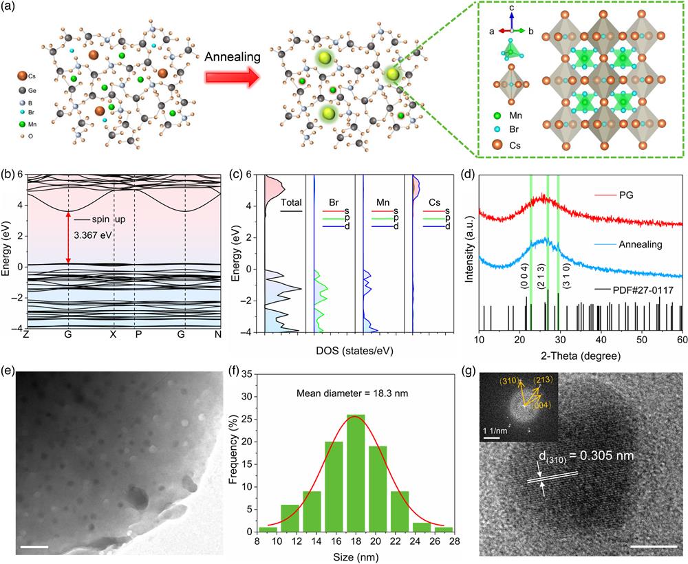
    Fig. 1. Structural properties of Cs3MnBr5 NCs crystallized in the glass. (a) Schematic diagram of glass network structure before (left) and after (middle) annealing and the anti-perovskite structure of the Cs3MnBr5 crystal (right). (b) DFT-calculated band structures and (c) electronic density of states of the Cs3MnBr5 crystal. (d) XRD patterns of the PG and the glass sample after annealing at 570°C for 5 h. (e) TEM image, (f) corresponding size distribution, and (g) HRTEM image of the glass annealed at 530°C for 5 h. The inset in (g) is the fast Fourier transform pattern corresponding to the (310), (213), and (004) crystal facet. The scale bars in (e) and (g) are 100 and 10 nm, respectively.
    PL properties of Cs3MnBr5 NCs in the glass. (a) Tanabe–Sugano diagram of 3d5 electronic configuration of Mn2+ ions. (b) Absorption and (c) PL spectra of the PG and samples annealed at different temperatures for 5 h. The inset in (b) shows the photographs of the glass samples taken under daylight (top) and 365 nm UV light (bottom). (d) PLE mapping spectra of the glass sample annealed at 570°C for 5 h. (e) Fluorescence decay curves of Cs3MnBr5 NCs and (f) Mn2+ in glass annealed at different temperatures. The fitting curves are fitted with (e) single-exponential and (f) double-exponential, respectively. The excitation wavelength used in (c), (e), (f) is 365 nm.
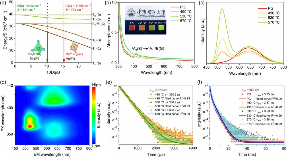
    Fig. 2. PL properties of Cs3MnBr5 NCs in the glass. (a) Tanabe–Sugano diagram of 3d5 electronic configuration of Mn2+ ions. (b) Absorption and (c) PL spectra of the PG and samples annealed at different temperatures for 5 h. The inset in (b) shows the photographs of the glass samples taken under daylight (top) and 365 nm UV light (bottom). (d) PLE mapping spectra of the glass sample annealed at 570°C for 5 h. (e) Fluorescence decay curves of Cs3MnBr5 NCs and (f) Mn2+ in glass annealed at different temperatures. The fitting curves are fitted with (e) single-exponential and (f) double-exponential, respectively. The excitation wavelength used in (c), (e), (f) is 365 nm.
    RL properties of Cs3MnBr5 NCs in the glass. (a) Schematic diagram of X-ray-induced luminescence mechanism of Cs3MnBr5 NCs and Mn2+ ions in the glass. (b) X-ray attenuation efficiency of Cs3MnBr5 NC-embedded glass, BGO, and CsPbBr3 crystal. (c) RL spectra of Cs3MnBr5 NC-embedded glass annealed at 570°C for different durations recorded under X-ray excitation with a dose rate of 4.814 mGyair s−1. The inset shows the photographs of the corresponding samples taken under X-ray irradiation. (d) RL spectra of the sample annealed at 570°C for 40 h recorded under different low X-ray dose rates. (e) Linear relationship between the low dose rate and RL intensity of the sample annealed at 570°C for 40 h.
    Fig. 3. RL properties of Cs3MnBr5 NCs in the glass. (a) Schematic diagram of X-ray-induced luminescence mechanism of Cs3MnBr5 NCs and Mn2+ ions in the glass. (b) X-ray attenuation efficiency of Cs3MnBr5 NC-embedded glass, BGO, and CsPbBr3 crystal. (c) RL spectra of Cs3MnBr5 NC-embedded glass annealed at 570°C for different durations recorded under X-ray excitation with a dose rate of 4.814  mGyairs1. The inset shows the photographs of the corresponding samples taken under X-ray irradiation. (d) RL spectra of the sample annealed at 570°C for 40 h recorded under different low X-ray dose rates. (e) Linear relationship between the low dose rate and RL intensity of the sample annealed at 570°C for 40 h.
    Demonstrations for real-time radiography. (a) The schematic of the X-ray imaging system. (b) Photographs of an AI chip (left), charging cable (middle), and circuit board (right) under daylight and X-ray irradiation. Scale bars, 1 cm. (c) Bright-field and X-ray images of the standard X-ray resolution pattern plate with the Cs3MnBr5 NC-embedded glass. (d) MTF of X-ray images obtained from the Cs3MnBr5 NC-embedded glass (the thickness is 0.6 mm). (e) Comparisons of spatial resolutions in representative scintillators.9" target="_self" style="display: inline;">9,16" target="_self" style="display: inline;">16–18" target="_self" style="display: inline;">–18,44" target="_self" style="display: inline;">44–46" target="_self" style="display: inline;">–46 (f) Real-time dynamic X-ray images recording the procedure of two-dimensional rotation of an iron spring; the speed of angular velocity is π/12 rad s−1 (Video 1, MP4, 14 MB [URL: https://doi.org/10.1117/1.AP.5.4.046002.s1]). Scale bar, 5 mm.
    Fig. 4. Demonstrations for real-time radiography. (a) The schematic of the X-ray imaging system. (b) Photographs of an AI chip (left), charging cable (middle), and circuit board (right) under daylight and X-ray irradiation. Scale bars, 1 cm. (c) Bright-field and X-ray images of the standard X-ray resolution pattern plate with the Cs3MnBr5 NC-embedded glass. (d) MTF of X-ray images obtained from the Cs3MnBr5 NC-embedded glass (the thickness is 0.6 mm). (e) Comparisons of spatial resolutions in representative scintillators.9,1618" target="_self" style="display: inline;">18,4446" target="_self" style="display: inline;">46 (f) Real-time dynamic X-ray images recording the procedure of two-dimensional rotation of an iron spring; the speed of angular velocity is π/12  rads1 (Video 1, MP4, 14 MB [URL: https://doi.org/10.1117/1.AP.5.4.046002.s1]). Scale bar, 5 mm.
    Ultrastable X-ray imaging. (a) Temperature-dependent RL spectra and (b) emission mapping of the glass sample under X-ray irradiation with a dose rate of 4.814 mGyair s−1. (c) RL intensity of the Cs3MnBr5 NCs in the glass sample upon six heating/cooling cycling processes over the temperature ranging from 303 to 563 K. (d) Photographs of a cylindrical ABS resin embedded with an iron spring in the air (top) and dimethyl silicone oil (bottom). (e) Thermal imaging photographs (top) and X-ray images (bottom) of the cylindrical ABS resin embedded with an iron spring immersed in dimethyl silicone oil at different temperatures. Scale bar, 1 cm. (f) RL intensity of Cs3MnBr5 NCs in the glass recorded over continuous 120 on/off cycles during 60 min. (g) Photograph (left) and X-ray images (right) of the chip taken under continuous irradiation for 2 h. Scale bar, 2 mm.
    Fig. 5. Ultrastable X-ray imaging. (a) Temperature-dependent RL spectra and (b) emission mapping of the glass sample under X-ray irradiation with a dose rate of 4.814  mGyairs1. (c) RL intensity of the Cs3MnBr5 NCs in the glass sample upon six heating/cooling cycling processes over the temperature ranging from 303 to 563 K. (d) Photographs of a cylindrical ABS resin embedded with an iron spring in the air (top) and dimethyl silicone oil (bottom). (e) Thermal imaging photographs (top) and X-ray images (bottom) of the cylindrical ABS resin embedded with an iron spring immersed in dimethyl silicone oil at different temperatures. Scale bar, 1 cm. (f) RL intensity of Cs3MnBr5 NCs in the glass recorded over continuous 120 on/off cycles during 60 min. (g) Photograph (left) and X-ray images (right) of the chip taken under continuous irradiation for 2 h. Scale bar, 2 mm.
    Yakun Le, Xiongjian Huang, Hao Zhang, Zhihao Zhou, Dandan Yang, Bozhao Yin, Xiaofeng Liu, Zhiguo Xia, Jianrong Qiu, Zhongmin Yang, Guoping Dong. Transparent glassy composites incorporating lead-free anti-perovskite halide nanocrystals enable tunable emission and ultrastable X-ray imaging[J]. Advanced Photonics, 2023, 5(4): 046002
    Download Citation