• Opto-Electronic Advances
  • Vol. 7, Issue 1, 230108 (2024)
Yuncheng Liu1、†, Ke Xu1、†, Xuhao Fan1, Xinger Wang1, Xuan Yu1, Wei Xiong1、2、*, and Hui Gao1、2、**
Author Affiliations
  • 1Wuhan National Laboratory for Optoelectronics and School of Optical and Electronic Information, Huazhong University of Science and Technology, Wuhan 430074, China
  • 2Optics Valley Laboratory, Wuhan 430074, China
  • show less
    DOI: 10.29026/oea.2024.230108 Cite this Article
    Yuncheng Liu, Ke Xu, Xuhao Fan, Xinger Wang, Xuan Yu, Wei Xiong, Hui Gao. Dynamic interactive bitwise meta-holography with ultra-high computational and display frame rates[J]. Opto-Electronic Advances, 2024, 7(1): 230108 Copy Citation Text show less
    Schematic diagram of the channel division concept of Bit-MH and the system for implementing interactive holographic games. The numbers and box lines are added to indicate the channel area; states 0 and 1 indicate corresponding position channel off and on, respectively. (a) Schematic of the concept of space channel division and the independent projection of each channel. (b) Schematic of selective turn-on channels for combined display. (c) Schematic diagram of the architecture of the interactive dynamic metasurface holographic game system. On the DMD, black indicates off, and white indicates on; on the metasurface device, the darker area indicates not being turned on.
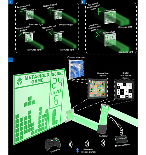
    Fig. 1. Schematic diagram of the channel division concept of Bit-MH and the system for implementing interactive holographic games. The numbers and box lines are added to indicate the channel area; states 0 and 1 indicate corresponding position channel off and on, respectively. (a) Schematic of the concept of space channel division and the independent projection of each channel. (b) Schematic of selective turn-on channels for combined display. (c) Schematic diagram of the architecture of the interactive dynamic metasurface holographic game system. On the DMD, black indicates off, and white indicates on; on the metasurface device, the darker area indicates not being turned on.
    Schematic comparison diagram between the bitwise dynamic holography algorithm and the traditional Fourier-based dynamic holography algorithm. For simplicity, a 7-bit digit tube is used as the target image; in our algorithm, the bit values 1 and 0 indicate that the corresponding channels are on and off, respectively; in the binary control image, white and black indicate that part of the channel is on and off, respectively; the box lines in the binary image are used to distinguish the different channels clearly and do not indicate other information. In the update mask of the bitwise algorithm, 0 and 1 respectively indicate that the channel at the corresponding position needs to be flipped or remain unchanged.
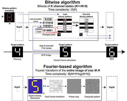
    Fig. 2. Schematic comparison diagram between the bitwise dynamic holography algorithm and the traditional Fourier-based dynamic holography algorithm. For simplicity, a 7-bit digit tube is used as the target image; in our algorithm, the bit values 1 and 0 indicate that the corresponding channels are on and off, respectively; in the binary control image, white and black indicate that part of the channel is on and off, respectively; the box lines in the binary image are used to distinguish the different channels clearly and do not indicate other information. In the update mask of the bitwise algorithm, 0 and 1 respectively indicate that the channel at the corresponding position needs to be flipped or remain unchanged.
    Design scheme of cylindric nanopillar with varying radii and same height. (a) Geometric parameters of the nanocylinder located in the center of the square lattice, W is the side length of the square lattice, and R and H are the radius and height of the nanocylinder, respectively. (b) Results of parameter sweep for the parameter range of R from 55 nm to 160 nm for W = 440 nm, H = 700 nm, and λ = 532 nm. Marked in the figure is the amount of amplitude and phase modulation provided by the selected nanopillars. (c) Characterization results of the CLSM of the device; The block-by-block partitions are different channel areas, and the detailed design is described in a later section. (d) Characterization results of the SEM of one local part of the device.
    Fig. 3. Design scheme of cylindric nanopillar with varying radii and same height. (a) Geometric parameters of the nanocylinder located in the center of the square lattice, W is the side length of the square lattice, and R and H are the radius and height of the nanocylinder, respectively. (b) Results of parameter sweep for the parameter range of R from 55 nm to 160 nm for W = 440 nm, H = 700 nm, and λ = 532 nm. Marked in the figure is the amount of amplitude and phase modulation provided by the selected nanopillars. (c) Characterization results of the CLSM of the device; The block-by-block partitions are different channel areas, and the detailed design is described in a later section. (d) Characterization results of the SEM of one local part of the device.
    Schematic diagram of arrangements, size, and display functions of the channels on the device for Tetris game. (a) The arrangement and size of channels on the overall designed device, which were marked based on the characterization result image of the metasurface device using CLSM. The numbers indicate the corresponding numbers of the channels. (b) Projection patterns from different channels that do not overlap when displayed. Static channel No. 24 display the fixed border and texts; cyclic channels No. 25 to 33 correspond to different poses of a rotating square, and opening these channels, in turn, realizes a dynamic pattern of rotating squares; cyclic channel No. 34 corresponds to a flashing music logo; multiplexed channels No. 35 to 133 are arrays of squares that form the main game canvas; multiplexed channels No. 1 to 21 and No. 134 to 141 project the digit tubes and simple array of squares illustrated on the right, respectively. (c) The text or pattern projection which was displayed in the center. To avoid possible mutual occlusion of patterns displayed in the same area, the text and patterns that would be projected in the center of the main scene are shown separately, corresponding to the (a) diagram, actual holograms of multiplexed channels No. 22 ("START" text), 23 ("GAME OVER" text), 24 ( the static borders and texts), 35 to 133 (square array in the main game canvas), 142 ("YOU WIN" text), 143 ("UPGRADE" text), 144 (fireworks pattern), respectively; for a clearer presentation, the static border is always displayed (channel numbered 24).
    Fig. 4. Schematic diagram of arrangements, size, and display functions of the channels on the device for Tetris game. (a) The arrangement and size of channels on the overall designed device, which were marked based on the characterization result image of the metasurface device using CLSM. The numbers indicate the corresponding numbers of the channels. (b) Projection patterns from different channels that do not overlap when displayed. Static channel No. 24 display the fixed border and texts; cyclic channels No. 25 to 33 correspond to different poses of a rotating square, and opening these channels, in turn, realizes a dynamic pattern of rotating squares; cyclic channel No. 34 corresponds to a flashing music logo; multiplexed channels No. 35 to 133 are arrays of squares that form the main game canvas; multiplexed channels No. 1 to 21 and No. 134 to 141 project the digit tubes and simple array of squares illustrated on the right, respectively. (c) The text or pattern projection which was displayed in the center. To avoid possible mutual occlusion of patterns displayed in the same area, the text and patterns that would be projected in the center of the main scene are shown separately, corresponding to the (a) diagram, actual holograms of multiplexed channels No. 22 ("START" text), 23 ("GAME OVER" text), 24 ( the static borders and texts), 35 to 133 (square array in the main game canvas), 142 ("YOU WIN" text), 143 ("UPGRADE" text), 144 (fireworks pattern), respectively; for a clearer presentation, the static border is always displayed (channel numbered 24).
    Experimental reconstructed patterns results at 473 nm, 532 nm, and 633 nm wavelength with partial channels turned on. In the coordinate axes, k0 represents the wave vector, and kx and ky represent the spatial frequencies in the x and y directions, respectively.k0 and kx and ky at 633 nm, 532 nm, and 573 nm use the corner markers of R, G, and B, respectively. In (a) and (b), The left side of each subgraph is the pattern and the right side is the diagram of the corresponding channel switching state; black and white refer to the channel close and open, respectively; some spacings are added around channels for clear presentation. (a) The reconstructed pattern of the fireworks. (b) A frame extracted from a game played via a gamepad. (c) The extracted stages of the actual playing game. Each of these four frames indicates continuous progress. (d) The on-the-fly created text uppercase letter 'I' symbol pattern result at 473 nm wavelength. (e) The on-the-fly created heart pattern result at 633 nm. (f) The on-the-fly created "HUST" text pattern result at 532 nm.
    Fig. 5. Experimental reconstructed patterns results at 473 nm, 532 nm, and 633 nm wavelength with partial channels turned on. In the coordinate axes, k0 represents the wave vector, and kx and ky represent the spatial frequencies in the x and y directions, respectively.k0 and kx and ky at 633 nm, 532 nm, and 573 nm use the corner markers of R, G, and B, respectively. In (a) and (b), The left side of each subgraph is the pattern and the right side is the diagram of the corresponding channel switching state; black and white refer to the channel close and open, respectively; some spacings are added around channels for clear presentation. (a) The reconstructed pattern of the fireworks. (b) A frame extracted from a game played via a gamepad. (c) The extracted stages of the actual playing game. Each of these four frames indicates continuous progress. (d) The on-the-fly created text uppercase letter 'I' symbol pattern result at 473 nm wavelength. (e) The on-the-fly created heart pattern result at 633 nm. (f) The on-the-fly created "HUST" text pattern result at 532 nm.
    Yuncheng Liu, Ke Xu, Xuhao Fan, Xinger Wang, Xuan Yu, Wei Xiong, Hui Gao. Dynamic interactive bitwise meta-holography with ultra-high computational and display frame rates[J]. Opto-Electronic Advances, 2024, 7(1): 230108
    Download Citation