1Wuhan National Laboratory for Optoelectronics and School of Optical and Electronic Information, Huazhong University of Science and Technology, Wuhan 430074, China
【AIGC One Sentence Reading】:This study introduces a novel interactive holographic system, achieving ultra-high computational and display frame rates, enabling smooth and real-time user engagement, paving the way for advanced dynamic meta-holography applications.
【AIGC Short Abstract】:This study introduces a novel dynamic and interactive holographic system utilizing bitwise metasurface technology, achieving unprecedented computational and display frame rates. By dividing the metasurface into multiple channels and using bitwise operations, the system enables smooth, real-time interactions and color display, demonstrated through an interactive holographic Tetris game. This technology opens new possibilities for advanced holography in human-computer interaction and virtual/augmented reality.
Note: This section is automatically generated by AI . The website and platform operators shall not be liable for any commercial or legal consequences arising from your use of AI generated content on this website. Please be aware of this.
Abstract
Interactive holography offers unmatched levels of immersion and user engagement in the field of future display. Despite of the substantial progress has been made in dynamic meta-holography, the realization of real-time, highly smooth interactive holography remains a significant challenge due to the computational and display frame rate limitations. In this study, we introduced a dynamic interactive bitwise meta-holography with ultra-high computational and display frame rates. To our knowledge, this is the first reported practical dynamic interactive metasurface holographic system. We spatially divided the metasurface device into multiple distinct channels, each projecting a reconstructed sub-pattern. The switching states of these channels were mapped to bitwise operations on a set of bit values, which avoids complex hologram computations, enabling an ultra-high computational frame rate. Our approach achieves a computational frame rate of 800 kHz and a display frame rate of 23 kHz on a low-power Raspberry Pi computational platform. According to this methodology, we demonstrated an interactive dynamic holographic Tetris game system that allows interactive gameplay, color display, and on-the-fly hologram creation. Our technology presents an inspiration for advanced dynamic meta-holography, which is promising for a broad range of applications including advanced human-computer interaction, real-time 3D visualization, and next-generation virtual and augmented reality systems.
Introduction
Computer-generated holography (CGH), combining holography with computer technology, enables the dynamic reconstruction of virtual objects, and has been widely used in diverse sectors including 3D display1, optical information storage2 and processing3, entertainment4, and encryption5, 6.
However, the reliance on devices like spatial light modulator (SLM)7 and the digital micro-mirror device (DMD)8 in traditional CGH systems has resulted in intrinsic display limitations such as a small field of view (FOV) and multiple orders of diffraction9. Recently, metasurfaces10, composed of numerous subwavelength nanostructures, have demonstrated remarkable capabilities in modulating electromagnetic waves (EM). By introducing abrupt changes in EM wave properties including amplitude, phase, and polarization10, meta-holography has made significant advancements in terms of large FOV11, 12, achromatic imaging13, color display14, 15, information capacity expansion16, multi-dimensional multiplexing17, and more, thereby becoming a potent tool for dynamic holography.
Dynamic meta-holography typically employs two methods: active and multiplexed schemes. Active schemes manipulate the basic properties of the unit structure using active materials like phase change materials18, 19, two-dimensional (2D) materials20, and various stimuli such as electrical21, 22, chemical6, 23, mechanical24, and environmental stimuli25. On the other hand, multiplexed schemes utilize the combination of static metasurfaces and dynamic modulation of the incident light field properties, such as incident angles26, polarization states27, 28, orbital angular momentum (OAM)29, space channel9, to display different holograms. Despite dynamic meta-holography's notable progress, it is still challenging to achieve real-time fluency to unlock more advanced functionalities in human-computer interaction and light field control systems responding to an external environment.
The key to high fluency in holography lies in the attainment of high computational and display frame rates. Computational frame rates, referring to the speed of data computation, processing, and preparation for display, ensure that the system can calculate the required content in real time. Many current schemes depend heavily on the continuous computation of the Fast Fourier Transform (FFT) one or more times and loading it onto the SLM/DMD. This often requires specialized computing units such as GPUs30, 31 to meet the high-speed refresh demands, making computational power and energy consumption significant limiting factors for large-scale applications. Display frame rates, on the other hand, referring to the speed at which a display device can refresh and present new contents. Active schemes for dynamically modulating metasurface devices and multiplexed schemes employing SLMs as dynamic refresh devices are difficult to attain high display frame rates, which affects the smoothness and dynamism of the visual content.
In this paper, we propose a bitwise meta-holography (Bit-MH) technology designed to achieve dynamic interactive holography with high computational and display frame rates. We spatially partition the display function of the metasurface into distinct channels with space channel multiplexing technology, each projecting a reconstructed sub-pattern. Efficient dynamic refreshing is achieved by mapping the switching states of the channels to a set of bit values and subsequently controlling the state of the channels via bitwise operations. Tests conducted on the computational platform utilized in this study resulted in a maximum computational frame rate of up to 800 kHz, and concurrently, the DMD used allowed for a maximum display frame rate of up to 23 kHz. As a proof of concept, we constructed an interactive holographic game system for the typical Tetris game in the visible region. Our design enables efficient dynamic updating of the hologram and allows interaction with external inputs. To our knowledge, this is the first demonstration of a practical interactive meta-holography system. We believe that the effective and programmable Bit-MH method can pave the way towards the realization of the seamlessly interactive holographic system.
Materials and methods
The design principle of Bit-MH
Our concept of bitwise meta-holography involves encoding and mapping the dynamic update process of the hologram as bitwise operations on a bit set. This technique permits efficient and unrestricted manipulation of the dynamic state of the hologram, circumventing any complex calculations such as Gerchberg-Saxton (G-S) iterative algorithms32 required for phase hologram computation. Benefiting from the high efficiency of bitwise operations, our approach allows for the high-speed execution of the dynamic refresh process.
In our design, the display functionality of the metasurface device is compartmentalized into multiple distinct channels, each of which projects an individual reconstructed sub-pattern, and the final displayed reconstructed image is composed of sub-patterns from all activated channels together. Dynamic refresh is achieved by selectively turning these channels on or off. The switching state of each channel is encoded as a bit value, and the collective states of all channels are consolidated into a bit set. Efficient dynamic refreshing can be achieved by performing bitwise operations on this bit set.
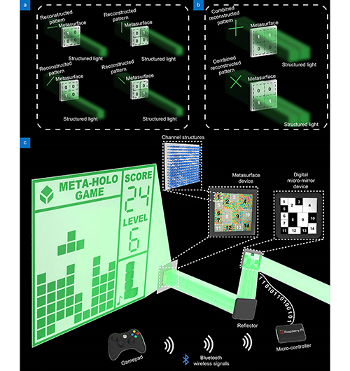
Since our scheme aims to control the states of multiple channels efficiently, the division of channels can be achieved via techniques such as space channel multiplexing9 and OAM channel multiplexing29. In this paper, we predominantly employed space channel multiplexing to spatially divide the metasurface device into channel regions with different sizes, positions, and display functions. A conceptual schematic of the spatial division and selective control of the divided channel area is shown in Fig. 1(a) and 1(b). The DMD is used to dynamically modulate the incident light at high speed, thereby controlling the switching states of channels in different positions. The simple binary control pattern loaded onto the DMD is continuously updated based on these bit values (e.g., bit 0 indicates ‘off ’ and displays black, while bit 1 indicates ‘on’ and displays white). The overall architecture of the interactive holographic gaming system used to demonstrate our bitwise dynamic meta-holography is shown in Fig. 1(c). It also incorporates a Bluetooth wireless gamepad controller for receiving dynamic control input from the user and a low-power embedded microcontroller for computational and device interconnectivity purposes.
Figure 1.Schematic diagram of the channel division concept of Bit-MH and the system for implementing interactive holographic games. The numbers and box lines are added to indicate the channel area; states 0 and 1 indicate corresponding position channel off and on, respectively. (a) Schematic of the concept of space channel division and the independent projection of each channel. (b) Schematic of selective turn-on channels for combined display. (c) Schematic diagram of the architecture of the interactive dynamic metasurface holographic game system. On the DMD, black indicates off, and white indicates on; on the metasurface device, the darker area indicates not being turned on.
In traditional dynamic holography, the hologram update process relies on the continuous usage of the FFT algorithm to compute the hologram that’s loaded onto a dynamic refresh device such as a DMD. This method necessitates the computation of the entire image each time, resulting in a time complexity of up to (the time complexity of the FFT algorithm) per computation, where and represent the number of pixels in the rows and columns of the target image, respectively.
Our approach segregates the hologram into sub-holograms (typically, is considerably smaller than the number of image pixels ), so the time complexity for managing the display state of all sub-holograms is . Our bitwise algorithm exhibits linear time complexity, which is a significant improvement over the square time complexity characteristic of traditional methods. Given that, in reality, not all holograms need to be updated, and each region on the binary control pattern fed to the DMD is independent, we are permitted to make on-demand adjustments each time. Our bitwise operation method swiftly and easily identifies the altered parts between two states via an exclusive OR operation, enabling us to compute an update mask to direct the next control pattern generation strategy. Figure 2 illustrates the core algorithm differences between our Bit-MH and traditional Fourier-based dynamic holography for updating the hologram.
Figure 2.Schematic comparison diagram between the bitwise dynamic holography algorithm and the traditional Fourier-based dynamic holography algorithm. For simplicity, a 7-bit digit tube is used as the target image; in our algorithm, the bit values 1 and 0 indicate that the corresponding channels are on and off, respectively; in the binary control image, white and black indicate that part of the channel is on and off, respectively; the box lines in the binary image are used to distinguish the different channels clearly and do not indicate other information. In the update mask of the bitwise algorithm, 0 and 1 respectively indicate that the channel at the corresponding position needs to be flipped or remain unchanged.
To compare the computational time complexities of two algorithms directly, we executed benchmark measurements on this demonstration platform focusing on computational frame rate generation speed with 600 × 600 pixels image. The computational frame rate generation speed of our method can reach up to 800 kHz, while the single Fourier transform can achieve approximately 30 Hz. On our computing platform, our methodology can enhance the computational frame rate by more than about times. Detailed benchmark measurement specifics can be found Supplementary information Section 1. The benchmark testing aimed to highlight the performance disparity between our bitwise algorithm and the traditional Fourier-based algorithms (e.g., G-S iterative optimization algorithm), during the pivotal phase of hologram generation in holographic display systems. Moreover, the dynamic refresh device in our system, the DMD (Texas Instruments, DLP9500), could provide a display frame rate of up to 23 kHz, empowering our system to achieve high-performance time-sequential cycle-based color display33 and refined grayscale display.
The design and setup of the interactive Tetris holographic game system
For the purpose of demonstrating Bit-MH actually, we designed and constructed a polarization-insensitive dielectric metasurface device that operates in transmission mode within the visible light band for an interactive Tetris game system.
We chose a silicon nitride nanopillar with a circular cross-section with different radii and 700 nm height. Each nanopillar is located on a silica square substrate of 440 nm period and is illustrated in Fig. 3(a). The radii of nanostructures vary from 61 nm to 153 nm. The electromagnetic response characteristics of nanopillars of different sizes under the incident light with the wavelength of 532 nm were simulated with the finite-difference time-domain (FDTD) method, and we chose eight radii for fabrication. The amount of phase modulation provided by selected nanopillars can cover the whole 2π range, while all nanopillars had high transmittance (Fig. 3(b)).
Figure 3.Design scheme of cylindric nanopillar with varying radii and same height. (a) Geometric parameters of the nanocylinder located in the center of the square lattice, W is the side length of the square lattice, and R and H are the radius and height of the nanocylinder, respectively. (b) Results of parameter sweep for the parameter range of R from 55 nm to 160 nm for W = 440 nm, H = 700 nm, and λ = 532 nm. Marked in the figure is the amount of amplitude and phase modulation provided by the selected nanopillars. (c) Characterization results of the CLSM of the device; The block-by-block partitions are different channel areas, and the detailed design is described in a later section. (d) Characterization results of the SEM of one local part of the device.
Finally, we fabricated our metasurface device according to the designed geometries of nanopillars using electron beam lithography (EBL). The optical image of the processed device characterized by the confocal laser scanning microscope (CLSM) is shown in Fig. 3(c). Additionally, the image of a local part of the device characterized by scanning electron microscopy (SEM) is depicted in Fig. 3(d).
To satisfy the dynamic and rich display requirements of the interactive game, we have carefully designed and divided the functions of the different channels. The channels, which consistently display throughout the game, were termed static channels; the channels, which cyclically display a set of patterns, were referred to as cyclic channels; and the channels, which display according to the game state, were called multiplexed channels. In an actual game process, all channels can supply up to different effective frames. However, all channels in our design were programmable, allowing for a maximum of up to different theoretical frames.
We have designed 144 channel regions with varying functions for the Tetris game (The size of the hologram was 3000 rows and 3000 columns of pixels). The division and arrangement of the channels with diverse shapes and size proportions across the entire device are illustrated in Fig. 4(a). We compensated the intensity of the reconstructed pattern at the edge position by adjusting the device region area of different types of channel regions. Furthermore, we made pre-compensation for pattern distortion, ensuring that reconstructed patterns on the flat screen always matched the target pattern. Detailed descriptions of distortion compensation can be found in Supplementary information Section 2. The number of channels largely depends on the intended application scenario. In particular, the number of channels correlates with both the intricacy of the reconstructed pattern and the complexity of its motion trajectory. As the desired reconstructed pattern becomes more intricate and its motion trajectory more detailed, there tends to be an increase in the number of allocated channels. Detailed analysis and discussion are provided in Supplementary information Section 3.
Figure 4.Schematic diagram of arrangements, size, and display functions of the channels on the device for Tetris game. (a) The arrangement and size of channels on the overall designed device, which were marked based on the characterization result image of the metasurface device using CLSM. The numbers indicate the corresponding numbers of the channels. (b) Projection patterns from different channels that do not overlap when displayed. Static channel No. 24 display the fixed border and texts; cyclic channels No. 25 to 33 correspond to different poses of a rotating square, and opening these channels, in turn, realizes a dynamic pattern of rotating squares; cyclic channel No. 34 corresponds to a flashing music logo; multiplexed channels No. 35 to 133 are arrays of squares that form the main game canvas; multiplexed channels No. 1 to 21 and No. 134 to 141 project the digit tubes and simple array of squares illustrated on the right, respectively. (c) The text or pattern projection which was displayed in the center. To avoid possible mutual occlusion of patterns displayed in the same area, the text and patterns that would be projected in the center of the main scene are shown separately, corresponding to the (a) diagram, actual holograms of multiplexed channels No. 22 ("START" text), 23 ("GAME OVER" text), 24 ( the static borders and texts), 35 to 133 (square array in the main game canvas), 142 ("YOU WIN" text), 143 ("UPGRADE" text), 144 (fireworks pattern), respectively; for a clearer presentation, the static border is always displayed (channel numbered 24).
In our designed Tetris game, the No. 24 channel was a static channel displaying the main game scene with static borders and texts (S=1); channels No. 25 to 33 were cyclic channels that switched and refreshed at a fixed frequency to display a rotating cube (C=9); the rest of the 134 channels were multiplexed channels (M=134). Therefore, the design can achieve theoretical frame number , and effective frame number . Within the multiplexed channels, the central channel array of 11 rows and 9 columns displayed a basic squares array, showcasing the main game canvas; To the right, a portion of the channel array combined into a 2-digit digital tube, displaying the current game score, and another section combined into a 1-bit digital tube, displaying the current game level. Channel No. 34 flashed a music logo in rhythm with the music. Channels No. 134 to 141 were used to display a preview of the block that will appear next. Different channels' projection patterns and positions were detailed and visually represented in Fig. 4(b) and Fig. 4(c).
We utilize the DMD to produce the structured light field, governing the opening states of channel regions, thus there’s no limitation to channel’s shape. For simplicity, while preserving the study’s generality, we opted for a predominantly rectangular channel shape.
The control program running on the low-power embedded platform (Raspberry Pi 4b, 64-bit Raspbian operating system) was developed using C++ programming language, detailed software design and development contents are described Supplementary information Section 4. A regular gamepad (Microsoft Xbox wireless controller) was employed in communicating with the micro-controller (Raspberry Pi 4b, Raspberry Pi Foundation, UK) via a standard Bluetooth communication interface.
In the game process, when a control signal from the gamepad was received, the button identifier was decoded and obtained by the microcontroller. This identifier was then mapped to game action, such as block movement or rotation. Subsequent to the execution of the control operation, the current game states were verified, and the score and level information were updated. All necessary information was immediately encoded into the bit set of game states.
The DMD control module was concurrently running in the background, where the channel states were read, and the corresponding compact binary control pattern was rendered. This pattern was then written to the standard HDMI output terminal of the microcontroller for the transmission of control data to the DMD, affecting the modulation of the incident light field. This process was continuously executed in a high-speed loop, ensuring constant response to user input. Benefiting from our bitwise dynamic meta-holography technology, game systems that require high computational frame rates and display frames could be operated even on a low-power computing platform.
Results and discussion
We further demonstrate our interactive holographic game system based on Bit-MH through an actual experimental system. To our knowledge, this is the first demonstration of a practical interactive meta-holography system. The system's basic components were, in order, the laser light source, the DMD, the metasurface device, and the requisite optical components. The schematic diagram of the optical system can be found in Supplementary information Section 5 (in Fig. S6). In addition to the continuous execution of the game process, the control program had the ability to enter debug mode, allowing for arbitrary selection and toggling of several channels' on or off states.
For a more straightforward illustration, we began by freely manipulating the on/off states of channels in debug mode to display a static pattern composed of independent or combined reconstructed sub-patterns from different channels. A 532 nm laser was employed as the light source. We added dark gaps around each channel through the control program to suppress inter-channel crosstalk.
We activated a single channel indicating clearance fireworks to exhibit an independent sub-patterns, as shown in Fig. 5(a). We then played a Tetris game with a regular gamepad with the holographic display system. The rules and game logic were consistent with traditional Tetris. In Fig. 5(b), we showed a frame during the actual operational game with a gamepad and the switching state of the channel in that state to demonstrate the ability to combine displays by controlling multiple channels simultaneously.
Figure 5.Experimental reconstructed patterns results at 473 nm, 532 nm, and 633 nm wavelength with partial channels turned on. In the coordinate axes, k0 represents the wave vector, and kx and ky represent the spatial frequencies in the x and y directions, respectively.k0 and kx and ky at 633 nm, 532 nm, and 573 nm use the corner markers of R, G, and B, respectively. In (a) and (b), The left side of each subgraph is the pattern and the right side is the diagram of the corresponding channel switching state; black and white refer to the channel close and open, respectively; some spacings are added around channels for clear presentation. (a) The reconstructed pattern of the fireworks. (b) A frame extracted from a game played via a gamepad. (c) The extracted stages of the actual playing game. Each of these four frames indicates continuous progress. (d) The on-the-fly created text uppercase letter 'I' symbol pattern result at 473 nm wavelength. (e) The on-the-fly created heart pattern result at 633 nm. (f) The on-the-fly created "HUST" text pattern result at 532 nm.
In Fig. 5(c), we demonstrated four extracted scenes from the continuous gameplay. In Supplementary information Section 7, we provided three videos, two showing the complete game-over process, game clearance, and the dynamic DMD control pattern of the corresponding channel states, and another video demonstrating the gameplay process using a gamepad. We believe these three videos visually and efficiently present all the design elements described in the previous section and a seamless interaction process of our holographic game system.
Furthermore, our scheme can enable color display and the real-time combination of basic sub-patterns. The capability of the Bit-MH allowed us to efficiently manipulate different channels simultaneously, which, in addition to the interactive game demonstrated earlier, allowed for the flexible combination of different sub-patterns to improvise unplanned patterns.
To exemplify this, we used the array of squares in the main game scene area to construct more complex patterns composed of basic squares independent of the game and without predefinition. In the debug mode of our control program, we activated the corresponding channels based on the content of the temporarily conceived pattern, immediately generating the desired pattern. We displayed a blue uppercase text ‘I’ text pattern at 473 nm, a red heart pattern at 633 nm, and a “HUST” text pattern of the school logo in green at 532 nm, as shown in Fig. 5(d–f), respectively. It’s important to emphasize that these complex patterns created on-the-fly are not constrained to manual construction using our control program; they can be generated dynamically, based entirely on external input control signals.
Finally, we employed a power meter to measure the optical power impinging upon the entire metasurface (), the power of the light transmitted from the metasurface (), and the optical power of the unmodulated laser beam (zero-order light) (). The overall efficiency is defined as . Based on this, we obtained the overall experimental efficiency to be 67.02% at 633 nm, 61.18% at 532 nm, and 51.54% at 473 nm, respectively.
Experimental results validated that our bitwise dynamic meta-holography scheme offers the high computational and display frame rates required by interactive holographic systems, for instance, and retains substantial manipulation flexibility.
Conclusions
In this paper, we introduced a dynamic interactive bitwise meta-holography that enables dynamic holographic displays with ultra-high computational and display frame rates. The metasurface device was spatially divided into multiple different channel regions, each of which projects a reconstructed sub-pattern. The process of updating the hologram was mapped to bitwise operations on a set of bit values, thus avoiding any complex hologram computation during dynamic refresh. These bitwise operations not only enable efficient computation, but also facilitate the quick and simple construction of update masks for on-demand alterations, thereby significantly reducing computational demands. Our methodology requires very low computational power and can be executed even on low-power computing devices at high speed. On the Raspberry Pi computational platform as demonstrated, we measured a maximum computational frame rate of up to 800 kHz, and the DMD provided a maximum display frame rate of up to 23 kHz.
Furthermore, modern CPUs provide vectorized instructions, such as Single Instruction and Multiple Data (SIMD), which enable simultaneous operation on many bit values. Owing to the partitioned control and simplicity of image structure, our strategy can effectively utilize vectorized instructions and parallel programming techniques to further boost the efficiency of bitwise operations and image generation.
The unmodulated zero-order light observed in the experimental results can be eliminating through filtering, tailored device design, and refining hologram computation algorithms. Implementing these measures can significantly boost efficiency and improve the quality of the hologram. Detailed methods for eliminating zero-order light are described in the Supplementary information Section 6.
While the overall device in this study was primarily designed for the Tetris game, by strategically planning the basic meta-display patterns, our scheme has the potential to generate many complexes and undefined patterns on the fly with flexible and efficient dynamic control, promising candidate for building a general-purpose dynamic meta-holography system. Notably, our system allows for expanding more prosperous interaction methods, such as gesture control34, further integrating the advantages of meta-holography with actual interaction. And it allows the extension to other multi-channel multiplexing technologies, such as OAM multiplexing, which, combined with the ultra-high computational frame rate characteristic of our Bit-MH, allows for more specific and specialized light field automation control, such as light-controlled array switches, spatial optical communications, optical computing, which can offer high-speed and flexible modulation capabilities for light field transformation.
Our proposed dynamic interactive bitwise meta-holography can inspire the related field, offering a practical and powerful approach for advanced human-computer interaction, real-time 3D visualization, and next-generation virtual and augmented reality systems, etc.
 AI Video Guide
  AI Picture Guide
 AI One Sentence