
Hongfan Zhu, Mo Sha, Huaping Zhao, Yuting Nie, Xuhui Sun, Yong Lei. Highly-rough surface carbon nanofibers film as an effective interlayer for lithium–sulfur batteries[J]. Journal of Semiconductors, 2020, 41(9): 092701
- Journal of Semiconductors
- Vol. 41, Issue 9, 092701 (2020)
Abstract
1. Introduction
Due to the rapid development of electrical vehicles and portable electronic devices, rechargeable batteries with low-cost and high energy density are in great demand[
So far many strategies have been proposed to address these abovementioned obstacles with the majority focusing on the cathode modification, such as embedding sulfur in/on various forms of carbon or surface coating of sulfur with conductive polymers or oxides[
Electrospinning is a simple fiber formation technique that applies a strong electric field to pull or thin out a polymer solution or melt jet forming nanofibers and these nanofibers inherently constitute a free-standing non-woven nanofiber mat[
2. Experimental
2.1. Synthesis
The N-CNFs with highly-rough surface were synthesized by an electrospinning process. At first, the precursor solution of PAN (Mw = 52 000) and PVP (Mw = 20 000) was prepared. Secondly, 0.6 g PAN was dissolved in 10 mL dimethylformamide (DMF) to form a faint yellow solution at 60 °C under stirring for 2 h. Lastly, 0.4 g PVP was added to the precursor solution under stirring over 24 h to obtain a mixture solution for electrospinning. The electrospinning process is described below: The precursor solution was loaded into an injector and a voltage of 15 kV was applied by a high-voltage DC power supply unit. A distance of 15 cm between the nozzle tip and the aluminum foil and a flow rate of 0.5 mL/h was applied to electrospinning.
The as-collected nanofibers were stabilized in air at 250 °C with a heating rate of 5 °C/min for 2 h, and then the temperature was further improved to 450 °C with a heating rate of 5 °C/min to remove PVP in nanofibers. Subsequently, the nanofibers were carbonized at 600 °C in an Ar (95 vol%)/H2 (5 vol%) atmosphere with 2 °C/min for 1 h to obtain N-CNFs with highly-rough surface. For comparison, PAN/PVP nanofibers were synthesized by stabilizing PAN/PVP nanofibers in the air at 250 °C without annealing at 450 °C and then directly carbonized in Ar (95 vol%)/H2 (5 vol%) atmosphere at 600 °C.
2.2. Characterization
The crystalline structure of the as-prepared N-CNFs were characterized by X-ray diffraction (XRD) (Empyrean, PANanlytical B.V.) equipped with Cu Kα radiation (λ = 0.15406 nm). The morphology and microstructure were observed by scanning electron microscopy (SEM, FEI Quanta-200) and by transmission electron microscopy (TEM, FEI Tecnai G2 F20 S-TWIN) with an accelerating voltage of 200 kV. Brunauer-Emmett-Teller (BET) was used to determine the specific surface area. The surface state and electronic structure were tested by using X-ray photoelectron spectroscopy (XPS) (Kratos AXIS UltraDLD ultrahigh vacuum (UHV) surface analysis system) using Al Ka radiation (1486 eV) as a probe. A thermal gravimetric-differential scanning calorimeter (TG-DSC, Q600, TA Instruments) measurement was used to analyze the thermal decomposition behavior for the N-CNFs in the air atmosphere.
2.3. Electrochemical measurements
The CMK-3/S composite (70% S content) was prepared by grinding CMK-3 and high-purity S powder with a mass ratio of 3 : 7 for 40 min. The active material paste was prepared by mixing CMK-3/S, conductive carbon black and polyvinylidene fluoride (PVDF) with a mass ratio of 7 : 2 : 1 in a N-methyl-2-pyrrolidinone solution. The slurry after grinding was cast onto an Al foil and dried at 60 °C in a vacuum oven for 12 h. The sulfur cathodes and N-CNFs mat were cut into circular disks with a diameter of 12 mm. The mass loading of the sulfur is about 1.4 mg/cm2 and the weight of a N-CNFs mat is around 0.9 mg. The cathode electrode and the N-CNFs mat were punched into circular discs with the same size. The electrolyte was 1 M lithium bis(trifluoromethanesulfonyl) imde (LiTFSI) in 1,3-dioxolane and 1,2-dimethoxyethane (DME-DOL 1 : 1 v/v). Coin cells of CR2032 were assembled in an argon-filled glove box with Li metal foil, polypropylene separator, N-CNFs interlayer and CMK-3/S cathode electrode in sequence. The galvanostatic charge-discharge tests were conducted on a LAND battery test system (CT2001A). Cyclic voltammetry (CV) measurements were tested by using a CHI 760E electrochemical workstation (ChenHua Instruments Co., China).
3. Results and discussion
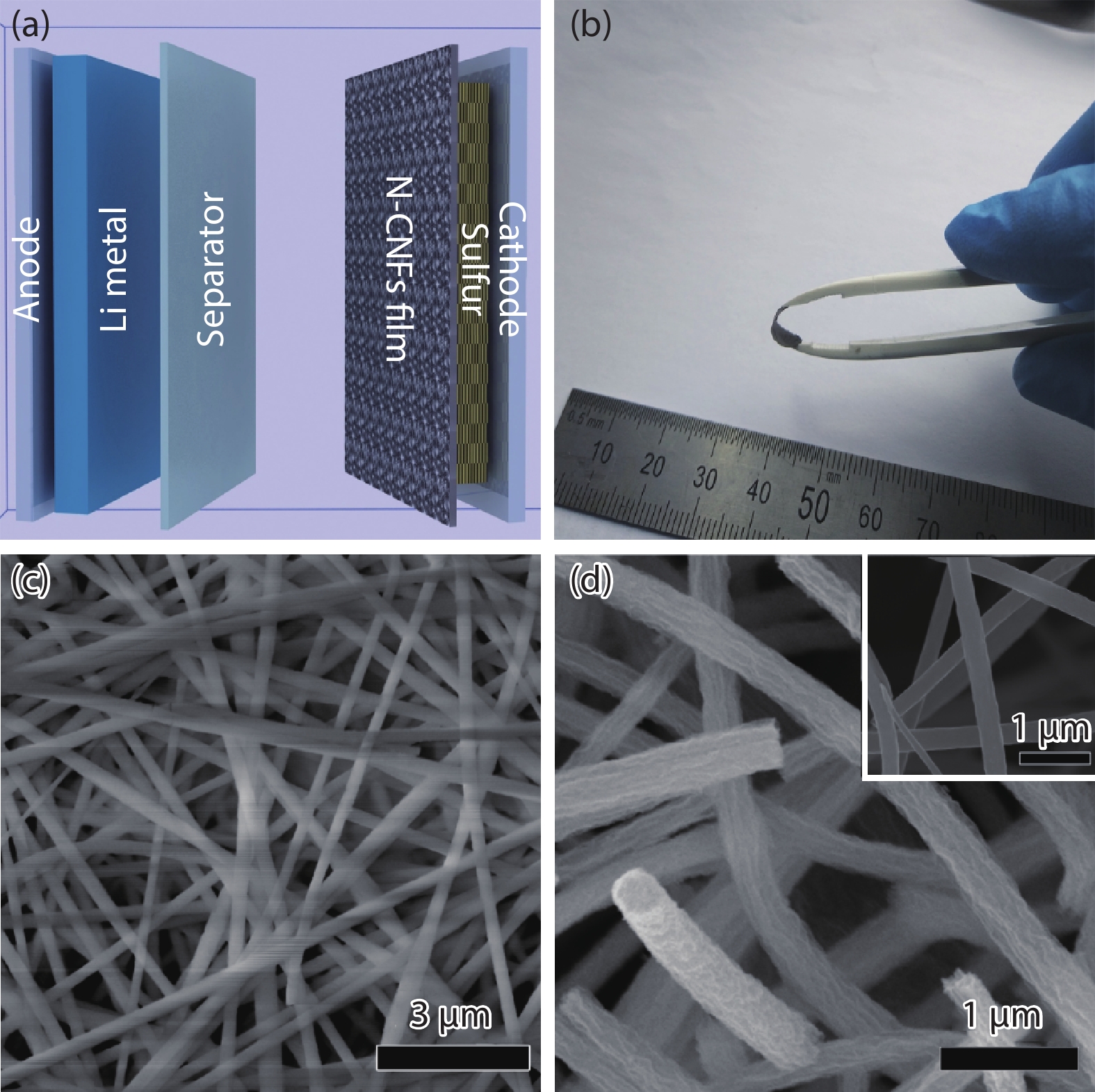
Fig. 1(a) illustrates the schematic of a Li–S battery with the functional N-CNFs film as the interlayer, in which the interlayer is sandwiched between the separator and sulfur cathode. The N-CNFs film is utilized to stabilize and trap the polysulfides moving from the cathode to the anode by shuttling effect, aiming to reducing their solubility in organic electrolyte and improving the utilization of the active materials. The as-obtained N-CNFs film exhibits excellent flexibility under a bending condition, which ensures the whole structure stability of the interlayer during cycling processes. The N-CNFs mat has the same size as the electrode and its diameter is about 12 mm, as illustrated in Fig. 1(b). Fig. 1(c) is the SEM image of as-spun PVP/PAN nanofibers. The nanofibers are continuous with a uniform diameter around 200 nm and their surface is quite smooth. After stabilization in air and the following carbonization, the as-obtained N-CNFs keeps the fibrous structure with no distinct structural changes compared to the as-spun PVP/PAN nanofibers except for a significantly increased surface roughness as shown in Fig. 1(d). In contrast, the surface of PAN/PVP nanofibers after carbonization is still smooth like the as-spun PVP/PAN nanofibers (inset). The rough surface of N-CNFs would effectively improve the ability of N-CNFs to intercept and adsorb polysulfides.
![]()
Figure 1.(Color online) (a) Schematic illustration of a Li–S cell configuration with a N-CNFs interlayer inserting between cathode and separator. (b) Digital image of a N-CNFs interlayer. (c, d) SEM images of the as-spun PAN/PVP nanofibers and the final N-CNFs (inset is the SEM image of the final PAN/PVP nanofibers).
The detailed microstructures of N-CNFs were further examined by TEM. As shown in Figs. 2(a)–2(c), the diameter of the N-CNFs is 150 nm and the grooves on the nanofiber surface confirm the rough surface. In addition, the high-angle annular-dark-field (HAADF) STEM images of a single nanofiber and element mappings for C and N are illustrated in Figs. 2(d)–2(f). As shown in the element mappings, the nanofibers content C and N elements, confirming the extensive N-doping in the CNFs. The XPS measurement was also performed to further identify the elemental composition of N-CNFs. Fig. 3(a) shows the general XPS spectrum of N-CNFs, which reveals N doping of the N-CNFs film, corresponding to the TEM mapping results. Fig. 3(b) shows the C 1s spectrum and the fitting peaks: C–C in aromatic rings at 284.9 eV, C–N at 285.8 eV, C–O at 286.7 eV, C=O at 288.1 eV, and O=C–O at 289.1 eV. Fig. 3(c) reveals three N 1s peaks at 398.3, 399.9, and 400.8 eV, corresponding to pyridinic, nitrile, and quaternary nitrogen, respectively. N-doping is an effective way to improve the performance for Li–S batteries. From the structure of the N species in the graphene layers, pyridinic N and nitrile could be highly chemically active because these N atoms stay in the edge sites[
![]()
Figure 2.(Color online) (a–c) TEM images of a single N-CNFs fiber. (d–f) HAADF STEM image and the element mappings for C and N, respectively.
![]()
Figure 3.(Color online) (a) XPS general spectrum of N-CNFs and the corresponding high resolution spectra of (b) C 1s and (c) N 1s.
The structural features of the N-CNFs film were examined by XRD, as shown in Fig. 4(a). There is a broad peak around 24° in the XRD pattern, and it should be corresponding to the typical (002) peak of graphite[
![]()
Figure 4.(Color online) (a) XRD pattern of N-CNFs. (b) Raman spectra of N-CNFs. (c) N2 adsorption/desorption isotherms of N-CNFs and PAN/PVP nanofibers. (d) Thermogravimetric analysis of N-CNFs in the air.
The electrochemical performance of Li–S batteries with or without interlayers are compared. Fig. 5(a) shows the charge/discharge voltage profiles of the battery at 0.1 C rate. Two discharge voltage plateaus arise at around 2.25 and 2.1 V, corresponding to two reduction reactions during the discharge process, respectively. In addition, a long voltage plateau appears around 2.3 V is related to a reverse oxidation process. The electrochemical behavior of the Li–S battery with an N-CNFs interlayer is analyzed using CV method. The CV data in the initial four cycles (Fig. 5(b)) are characteristics redox reactions for Li–S batteries. In the cathodic scan, two reduction peaks are appeared at around 2.7 and 2.1 V. The two peaks are representatively associated with an open-ring reduction reaction of S8 to long-chain Li2Sn (4 ≤ n ≤ 8) and a successive decomposition of Li2Sn into short-chain Li2S/ Li2S2, respectively. During the following anodic scan, a distinct sharp peak, appearing at 2.65 V, corresponds to the oxidation of Li2S/Li2S2 to Li2S8. The redox feature shows no obvious change in the four cycles, indicating highly reactive reversibility and good cyclability of the battery. The cycling performance of the Li–S batteries is plotted in Fig. 5(c). Li–S batteries with interlayers show obvious capacity improvement, comparing to the one without interlayer. In detail, all three batteries can deliver an initial discharge capacity of about 1200 mAh/g, but Li–S batteries with N-CNFs and PAN/PVP interlayers can keep high capacities about 785 and 630 mAh/g, respectively, after 200 cycles. In contrast, Li–S batteries without interlayers show a serious capacity degradation during test, and a very limited capacity of only 20 mAh/g is preserved after 200 cycles. Furthermore, the Li–S battery with N-CNFs exhibits better cycling stability than that of PAN/PVP interlayers. The improved cycling stability is considered to be benefited from the highly-rough surface N-CNFs interlayer which holds a stronger ability to trap sulfur on the cathode side and suppress the polysulfide solubility in the organic electrolyte, comparing to PAN/PVP interlayers. Fig. 5(d) shows rate cycling behaviors of the Li–S battery with an N-CNFs interlayer. The battery displays reversible capacities of 1204, 986, 900, 821, 741 and 573 mAh/g at rates of 0.1, 0.2, 0.5, 1, 2 and 5 C, respectively. Particularly, when the rate turns back to 0.2 C, the capacity recovers to 930 mAh/g, which shows the battery has a strong capacity stability under wide range of rates.
![]()
Figure 5.(Color online) Electrochemical performance of Li–S batteries with N-CNFs an interlayer. (a) Galvanostatic charge/discharge profiles at various cycles of the Li–S cells with a N-CNFs interlayer. (b) CV curves of the initial two cycles from 3.0 V to 1.0 V vs Li+/Li at a scan rate of 0.05 mV/s. (c) Cycling performance of the Li–S batteries using different interlayers and (d) rate capabilities at various current rates, from 0.1 C to 5 C and back to 0.2 C.
4. Conclusion
We use the highly-rough surface N-CNFs film as flexible interlayers and apply them in Li–S batteries. The highly-rough surface interlayer provides large surface area to stabilize polysulfides and suppress the solubility in organic electrolyte. Besides, N-doping gives the CNFs film good electrical conductivity, which can improve rate capacity for Li–S batteries. The Li–S battery with an N-CNFs interlayer displays a high discharge capacity 785 mAh/g after 200 cycles and good rate capability of 573 mAh/g at 5 C. The enhanced electrochemical performance demonstrates this highly-rough surface N-CNFs interlayer synthesized by electrospinning is a promising method to fabricate high capability Li–S batteries.
Acknowledgements
The work was supported by the Natural Science Foundation of China (NSFC) (Grant No. U1432249, 21203130) and the Priority Academic Program Development of Jiangsu Higher Education Institutions (PAPD). This work was also supported by the German Research Foundation (DFG: LE2249/5-1).
References
[1] C Zhang, Y Ma, X Zhang et al. Two-dimensional transition metal carbides and nitrides (MXenes): Synthesis, properties, and electrochemical energy storage applications. Energy Environ Mater, 3, 29(2020).
[2] Q He, B Yu, Z Li et al. Density functional theory for battery materials. Energy Environ Mater, 2, 264(2019).
[3] W Tu, Y Wen, C Ye et al. Phase transformation of lithium-rich oxide cathode in full cell and its suppression by solid electrolyte interphase on graphite anode. Energy Environ Mater, 3, 19(2020).
[4] T Or, S W Gourley, K Kaliyappan et al. Recycling of mixed cathode lithium-ion batteries for electric vehicles: Current status and future outlook. Carbon Energy, 2, 6(2020).
[5] H Xu, C Peng, Y Yan et al. “All-in-one” integrated ultrathin SnS2@ 3D multichannel carbon matrix power high-areal–capacity lithium battery anode. Carbon Energy, 1, 276(2019).
[6] W Shin, J Lu, X Ji. ZnS coating of cathode facilitates lean-electrolyte Li–S batteries. Carbon Energy, 1, 165(2019).
[7] N Ding, S W Chien, T A Hor et al. Key parameters in design of lithium sulfur batteries. J Power Sources, 269, 111(2014).
[8] A Manthiram, Y Fu, Y S Su. Challenges and prospects of lithium–sulfur batteries. Acc Chem Res, 46, 1125(2013).
[9] Y Zang, F Pei, J Huang et al. Large-area preparation of crack-free crystalline microporous conductive membrane to upgrade high energy lithium –sulfur batteries. Adv Energy Mater, 8, 1802052(2018).
[10] S S Zhang. Liquid electrolyte lithium/sulfur battery: Fundamental chemistry, problems, and solutions. J Power Sources, 231, 153(2013).
[11] W J Chung, J J Griebel, E T Kim et al. The use of elemental sulfur as an alternative feedstock for polymeric materials. Nat Chem, 5, 518(2013).
[12] Y X Yin, S Xin, Y G Guo et al. Lithium–sulfur batteries: electrochemistry, materials, and prospects. Angew Chem Int Ed, 52, 13186(2013).
[13] L Chen, L L Shaw. Recent advances in lithium–sulfur batteries. J Power Sources, 267, 770(2014).
[14] S R Chen, Y P Zhai, G L Xu et al. Ordered mesoporous carbon/sulfur nanocomposite of high performances as cathode for lithium–sulfur battery. Electrochim Acta, 56, 9549(2011).
[15] G Wang, Y Lai, Z Zhang et al. Enhanced rate capability and cycle stability of lithium–sulfur batteries with a bifunctional MCNT@ PEG-modified separator. J Mater Chem A, 3, 7139(2015).
[16] J Park, B C Yu, J S Park et al. Tungsten disulfide catalysts supported on a carbon cloth interlayer for high performance Li–S battery. Adv Energy Mater, 7, 1602567(2017).
[17] H Li, L Sun, Y Zhang et al. Enhanced cycle performance of Li/S battery with the reduced graphene oxide/activated carbon functional interlayer. J Energy Chem, 26, 1276(2017).
[18] T Gao, T Le, Y Yang et al. Effects of electrospun carbon nanofibers’ interlayers on high-performance lithium–sulfur batteries. Materials, 10, 376(2017).
[19] Z Yuan, H J Peng, T Z Hou et al. Powering lithium–sulfur battery performance by propelling polysulfide redox at sulfiphilic hosts. Nano Lett, 16, 519(2016).
[20] G Ma, Z Wen, Q Wang et al. Enhanced performance of lithium sulfur battery with self-assembly polypyrrole nanotube film as the functional interlayer. J Power Sources, 273, 511(2015).
[21] T G Jeong, Y H Moon, H H Chun et al. Free standing acetylene black mesh to capture dissolved polysulfide in lithium sulfur batteries. ChemCommun, 49, 11107(2013).
[22] K Zhang, F Qin, J Fang et al. Nickel foam as interlayer to improve the performance of lithium–sulfur battery. J Solid State Electrochem, 18, 1025(2014).
[23] G Ma, Z Wen, J Jin et al. Enhanced cycle performance of Li–S battery with a polypyrrole functional interlayer. J Power Sources, 267, 542(2014).
[24] R Singhal, S H Chung, A Manthiram et al. A free-standing carbon nanofiber interlayer for high-performance lithium–sulfur batteries. J Mater Chem A, 3, 4530(2015).
[25] Z Zhang, G Wang, Y Lai et al. Nitrogen-doped porous hollow carbon sphere-decorated separators for advanced lithium–sulfur batteries. J Power Sources, 300, 157(2015).
[26] B P Williams, Y L Joo. Tunable large mesopores in carbon nanofiber interlayers for high-rate lithium sulfur batteries. J Electrochem Soc, 163, A2745(2016).
[27] L Zeng, F Pan, W Li et al. Free-standing porous carbon nanofibers-sulfur composite for flexible Li–S battery cathode. Nanoscale, 6, 9579(2014).
[28] Y S Su, A Manthiram. A new approach to improve cycle performance of rechargeable lithium–sulfur batteries by inserting a free-standing MWCNT interlayer. Chem Commun, 48, 8817(2012).
[29] W Kong, L Yan, Y Luo et al. Ultrathin MnO2/graphene oxide/carbon nanotube interlayer as efficient polysulfide-trapping shield for high-performance Li–S batteries. Adv Funct Mater, 27, 1606663(2017).
[30] X Wang, Z Wang, L Chen. Reduced graphene oxide film as a shuttle-inhibiting interlayer in a lithium–sulfur battery. J Power Sources, 242, 65(2013).
[31] G Zhou, L Li, D W Wang et al. A flexible sulfur-graphene-polypropylene separator integrated electrode for advanced Li–S batteries. Adv Mater, 27, 641(2015).
[32] G Liang, J Wu, X Qin et al. Ultrafine TiO2 decorated carbon nanofibers as multifunctional interlayer for high-performance lithium–sulfur battery. ACS Appl Mater Interfaces, 8, 23105(2016).
[33] M Sha, H Zhang, Y Nie et al. Sn nanoparticles@nitrogen-doped carbon nanofiber composites as high-performance anodes for sodium-ion batteries. J Mater Chem A, 5, 6277(2017).
[34] M M Demir, I Yilgor, E Yilgor et al. Electrospinning of polyurethane fibers. Polymer, 43, 3303(2002).
[35] L Wang, Y Yu, P Chen et al. Electrospinning synthesis of C/Fe3O4 composite nanofibers and their application for high performance lithium-ion batteries. J Power Sources, 183, 717(2008).
[36] X Wang, Q Weng, X Liu et al. Atomistic origins of high rate capability and capacity of N-doped graphene for lithium storage. Nano Lett, 14, 1164(2014).
[37] S Wang, K Zou, Y Qian et al. Insight to the synergistic effect of N-doping level and pore structure on improving the electrochemical performance of sulfur/N-doped porous carbon cathode for Li–S batteries. Carbon, 144, 745(2019).
[38] N Hellgren, J Guo, C Såthe et al. Nitrogen bonding structure in carbon nitride thin films studied by soft X-ray spectroscopy. Appl Phys Lett, 79, 4348(2001).
[39] J Xu, M Wang, N P Wickramaratne et al. High-performance sodium ion batteries based on a 3D anode from nitrogen-doped graphene foams. Adv Mater, 27, 2042(2015).
[40] T H Le, Y Yang, L Yu et al. Polyimide-based porous hollow carbon nanofibers for supercapacitor electrode. J Appl Polym Sci, 133(2016).
[41] J Pandey, P Prajapati, M R Shimpi et al. Studies of molecular structure, hydrogen bonding and chemical activity of a nitrofurantoin-L-proline cocrystal: a combined spectroscopic and quantum chemical approach. RSC Adv, 6, 74135(2016).

Set citation alerts for the article
Please enter your email address
© Copyright 2018-2021 | Chinese Laser Press. All Rights Reserved 沪ICP备15018463号-20