
Xiaoheng Wang, Qingsheng Xue. Optical Design of Portable Non-Mydriatic Fundus Camera with Large Field of View[J]. Acta Optica Sinica, 2017, 37(9): 0922001
- Acta Optica Sinica
- Vol. 37, Issue 9, 0922001 (2017)
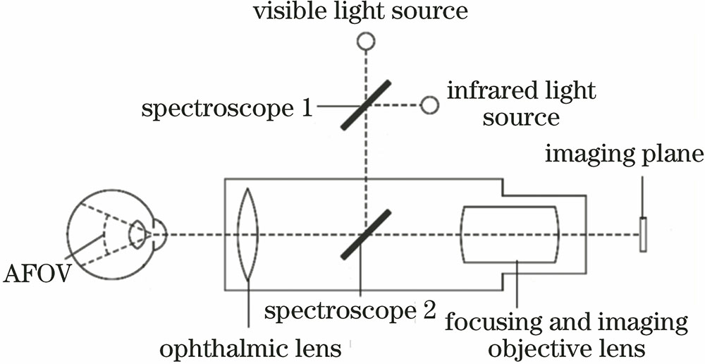
Fig. 1. Optical system structure of the fundus camera
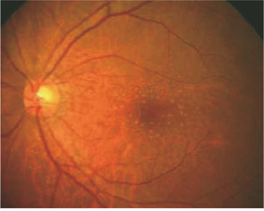
Fig. 2. Color image of the retina
Fig. 3. Eye model
Fig. 4. Structure of the ophthalmic lens. (a) Prototype; (b) optimization result
Fig. 5. Initial structure of the imaging system. (a) Without spectroscope; (b) with spectroscope
Fig. 6. Structure of the imaging system combined with eye model
Fig. 7. MTF curves of the imaging system
Fig. 8. Aberration analysis diagram. (a) Ray fan plot; (b) spot diagram; (c) field curvature and distortion
Fig. 9. Imaging simulation of the system. (a) Source image; (b) simulated image plane
Fig. 10. Schematic of the annular illumination
Fig. 11. Lighting system construction
Fig. 12. Schematic of the ring light source
Fig. 13. (a) MTF, (b) spot diagram and (c) relative illumination distribution of the illumination system
|
Table 1. Main designed specifications of the fundus camera
|
Table 2. Tolerance range of the optical system
|
Table 3. MTF of the imaging system at 70 lp/mm

Set citation alerts for the article
Please enter your email address
© Copyright 2018-2021 | Chinese Laser Press. All Rights Reserved 沪ICP备15018463号-20