• Photonics Research
  • Vol. 6, Issue 6, 574 (2018)
Jie Huang1, Junbo Yang1、2、*, Dingbo Chen1, Xin He1, Yunxin Han1, Jingjing Zhang1, and Zhaojian Zhang1
Author Affiliations
  • 1Center of Material Science, National University of Defense Technology, Changsha 410073, China
  • 2China State Key Laboratory on Advanced Optical Communication Systems and Networks, Peking University, Beijing 100871, China
  • show less
    DOI: 10.1364/PRJ.6.000574 Cite this Article Set citation alerts
    Jie Huang, Junbo Yang, Dingbo Chen, Xin He, Yunxin Han, Jingjing Zhang, Zhaojian Zhang. Ultra-compact broadband polarization beam splitter with strong expansibility[J]. Photonics Research, 2018, 6(6): 574 Copy Citation Text show less
    Schematic of the device. (a) Three-dimensional diagram. (b) Top view and side view. Fundamental TE mode and fundamental TM mode are coupled into the PBS from port 1, and after passing through the PBS, TE mode, and TM mode, are coupled out from port 3 and port 4, respectively.
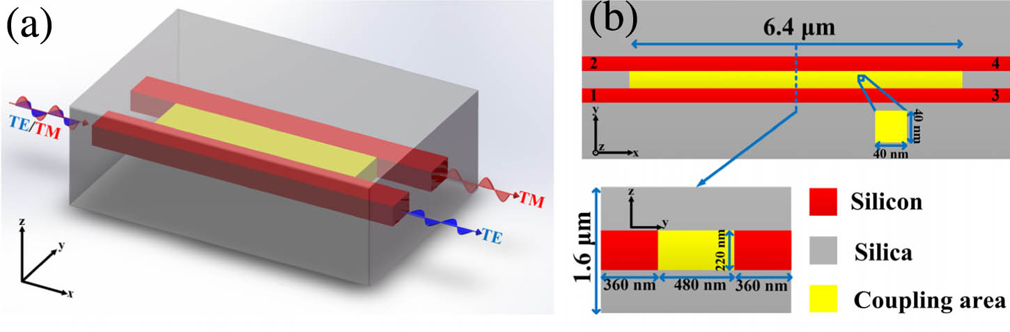
    Fig. 1. Schematic of the device. (a) Three-dimensional diagram. (b) Top view and side view. Fundamental TE mode and fundamental TM mode are coupled into the PBS from port 1, and after passing through the PBS, TE mode, and TM mode, are coupled out from port 3 and port 4, respectively.
    (a) Maximum value and minimum value of the effective indices of different modes as a function of wavelength, where the shaded part represents the overlap between TE0 (TM0) and TE1 (TM1). (b) Full-coupling lengths of the fundamental TE (solid line) and TM (dotted line) modes as a function of wavelength, where the blue line represents the maximum value, the red line represents the minimum value, the yellow (black) star represents the maximum (minimum) value of TE mode, the yellow (black) triangle represents the maximum (minimum) value of TM mode, and the black dashed line represents the position of the wavelength of 1310 nm and 1550 nm, respectively.
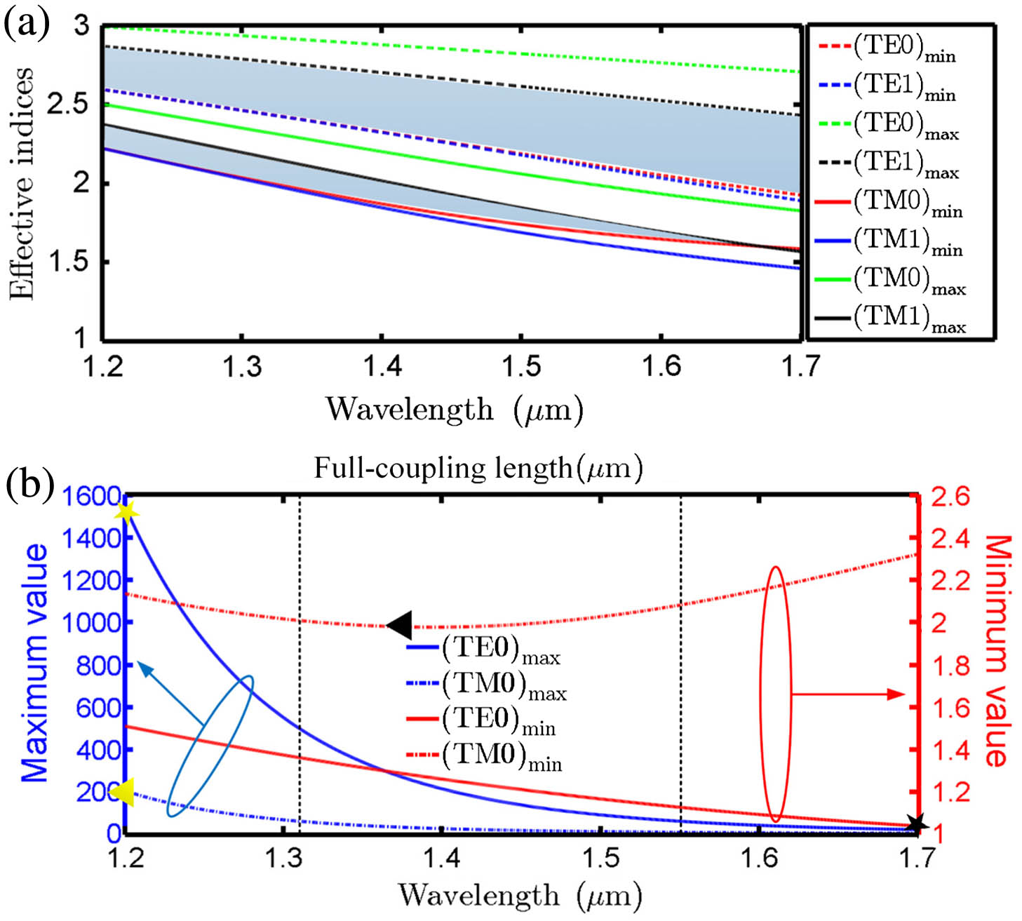
    Fig. 2. (a) Maximum value and minimum value of the effective indices of different modes as a function of wavelength, where the shaded part represents the overlap between TE0 (TM0) and TE1 (TM1). (b) Full-coupling lengths of the fundamental TE (solid line) and TM (dotted line) modes as a function of wavelength, where the blue line represents the maximum value, the red line represents the minimum value, the yellow (black) star represents the maximum (minimum) value of TE mode, the yellow (black) triangle represents the maximum (minimum) value of TM mode, and the black dashed line represents the position of the wavelength of 1310 nm and 1550 nm, respectively.
    Dependence of the performance of PBSs on coupling length, where the red (black) line and blue (green) line represent the power of TE (TM) modes to transmit to port 3 and port 4, respectively. To assure the convergence of the design process, the number of iterations is 300.
    Fig. 3. Dependence of the performance of PBSs on coupling length, where the red (black) line and blue (green) line represent the power of TE (TM) modes to transmit to port 3 and port 4, respectively. To assure the convergence of the design process, the number of iterations is 300.
    Design results at the wavelengths of 1310, 1550, and 1600 nm. (a)–(c) Grayscale map of the designed structures, where white represents silica and black represents silicon. (d)–(f) The distribution of electric field amplitude at the center of the devices. (g)–(i) The broadband transmission of the designed devices, where the red (blue) solid line represents the transmission of the TE mode at port 4 (3) and the red (blue) dashed line represents the transmission of TM mode at port 4 (3). In addition, the double-sided black arrow represents the target wavelength. The coupling lengths are 6.4 μm.
    Fig. 4. Design results at the wavelengths of 1310, 1550, and 1600 nm. (a)–(c) Grayscale map of the designed structures, where white represents silica and black represents silicon. (d)–(f) The distribution of electric field amplitude at the center of the devices. (g)–(i) The broadband transmission of the designed devices, where the red (blue) solid line represents the transmission of the TE mode at port 4 (3) and the red (blue) dashed line represents the transmission of TM mode at port 4 (3). In addition, the double-sided black arrow represents the target wavelength. The coupling lengths are 6.4 μm.
    Design results at the wavelength ranges of 1290–1350 nm, 1510–1570 nm, and 1570–1630 nm. The distances between multiple target wavelengths are 20 nm, which gives a 60 nm design bandwidth for each device. (a)–(c) Grayscale map of the designed structures, where white represents silica and black represents silicon. (d)–(f) The broadband transmission of the designed devices, where the red (blue) solid line represents the transmission of TE mode at port 4 (3), the red (blue) dashed line represents the transmission of TM mode at port 4 (3), and the double-sided black arrows represent the target wavelengths. (g)–(i) The ERs and ILs of the designed devices, where the wavelengths of ERs>14.5 dB and ILs<0.46 dB are 1286–1364 nm, 1497–1568 nm, and 1553–1634 nm. The definitions of ER and IL are −10×lg(transmission). For example, the ER and IL of TE mode are −10×lg(transmissioncross) and −10×lg(transmissionthrough), respectively. The coupling lengths are 6.4 μm.
    Fig. 5. Design results at the wavelength ranges of 1290–1350 nm, 1510–1570 nm, and 1570–1630 nm. The distances between multiple target wavelengths are 20 nm, which gives a 60 nm design bandwidth for each device. (a)–(c) Grayscale map of the designed structures, where white represents silica and black represents silicon. (d)–(f) The broadband transmission of the designed devices, where the red (blue) solid line represents the transmission of TE mode at port 4 (3), the red (blue) dashed line represents the transmission of TM mode at port 4 (3), and the double-sided black arrows represent the target wavelengths. (g)–(i) The ERs and ILs of the designed devices, where the wavelengths of ERs>14.5  dB and ILs<0.46  dB are 1286–1364 nm, 1497–1568 nm, and 1553–1634 nm. The definitions of ER and IL are 10×lg(transmission). For example, the ER and IL of TE mode are 10×lg(transmissioncross) and 10×lg(transmissionthrough), respectively. The coupling lengths are 6.4 μm.
    Jie Huang, Junbo Yang, Dingbo Chen, Xin He, Yunxin Han, Jingjing Zhang, Zhaojian Zhang. Ultra-compact broadband polarization beam splitter with strong expansibility[J]. Photonics Research, 2018, 6(6): 574
    Download Citation