
Ting Zhang, Ting Zhang, Sen Yang, Sen Yang, XinYing Yu, XinYing Yu. Tunable Broadband Terahertz Perfect Absorber Design Based on Vanadium Dioxide[J]. Laser & Optoelectronics Progress, 2021, 58(21): 2116002
- Laser & Optoelectronics Progress
- Vol. 58, Issue 21, 2116002 (2021)
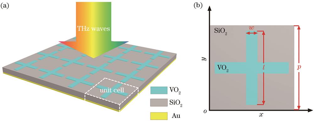
Fig. 1. Schematics of broadband terahertz metamaterial structure. (a) Schematic of cell array; (b) top view of cell structure

Fig. 1. Schematics of broadband terahertz metamaterial structure. (a) Schematic of cell array; (b) top view of cell structure
Fig. 2. Variations of absorptivity of the absorber, as well as the real and imaginary parts of permittivity of VO2 with conductivity. (a) Absorptivity; (b) real part of permittivity; (c) imaginary part of permittivity
Fig. 2. Variations of absorptivity of the absorber, as well as the real and imaginary parts of permittivity of VO2 with conductivity. (a) Absorptivity; (b) real part of permittivity; (c) imaginary part of permittivity
Fig. 3. Absorption curves of metamaterial perfect absorbers with and without VO2 under various SiO2 thicknesses
Fig. 3. Absorption curves of metamaterial perfect absorbers with and without VO2 under various SiO2 thicknesses
Fig. 4. Variations of real and imaginary parts of relative impedance under different VO2 conductivities. (a) Real part; (b) imaginary part
Fig. 4. Variations of real and imaginary parts of relative impedance under different VO2 conductivities. (a) Real part; (b) imaginary part
Fig. 5. Electric field intensity at two nearly perfect absorption peaks. (a) f1=0.82 THz; (b) f2=1.6 THz
Fig. 5. Electric field intensity at two nearly perfect absorption peaks. (a) f1=0.82 THz; (b) f2=1.6 THz
Fig. 6. Variations of absorptivity with incident angle and polarization angel. (a) Variation of absorptivity with incident angle at TE mode; (b) variation of absorptivity with incident angle at TM mode; (c) variation of absorptivity with polarization angles at TE mode
Fig. 6. Variations of absorptivity with incident angle and polarization angel. (a) Variation of absorptivity with incident angle at TE mode; (b) variation of absorptivity with incident angle at TM mode; (c) variation of absorptivity with polarization angles at TE mode


Set citation alerts for the article
Please enter your email address
© Copyright 2018-2021 | Chinese Laser Press. All Rights Reserved 沪ICP备15018463号-20