• Photonics Research
  • Vol. 11, Issue 1, 44 (2023)
Jie-Rong Cheng1、2, Yang Yang1, Sai Chen3, Qi-Ye Wen4, Yun-Yun Ji1、5, Fei Fan1、5, and Sheng-Jiang Chang1、5、*
Author Affiliations
  • 1Institute of Modern Optics, Nankai University, Tianjin 300350, China
  • 2Tianjin Key Laboratory of Micro-Scale Optical Information Science and Technology, Tianjin 300350, China
  • 3School of Electronic and Information Engineering, Beihang University, Beijing 100191, China
  • 4State Key Laboratory of Electronic Thin Films and Integrated Devices, University of Electronic Science and Technology of China, Chengdu 610054, China
  • 5Tianjin Key Laboratory of Optoelectronic Sensor and Sensing Network Technology, Tianjin 300350, China
  • show less
    DOI: 10.1364/PRJ.475131 Cite this Article Set citation alerts
    Jie-Rong Cheng, Yang Yang, Sai Chen, Qi-Ye Wen, Yun-Yun Ji, Fei Fan, Sheng-Jiang Chang. Continuous terahertz omnidirectional beam steering by dual diffraction of metagratings[J]. Photonics Research, 2023, 11(1): 44 Copy Citation Text show less
    (a) Schematic of the metagrating pair for omnidirectional beam steering through in-plane rotation. The orientation angles of each metagrating α1 and α2 are defined between the grating wave vector and the global x axis. (b) Details of the beam propagation through dual diffraction engineering.
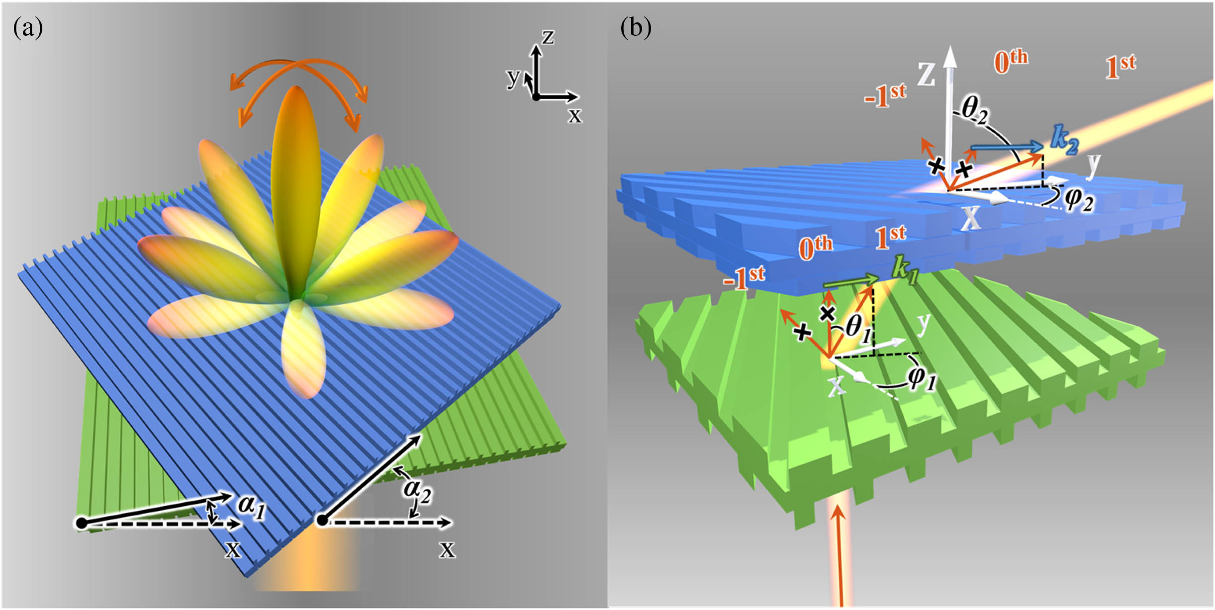
    Fig. 1. (a) Schematic of the metagrating pair for omnidirectional beam steering through in-plane rotation. The orientation angles of each metagrating α1 and α2 are defined between the grating wave vector and the global x axis. (b) Details of the beam propagation through dual diffraction engineering.
    (a), (b) Beam steering scheme using wave vector operation. The trajectory of the composed k// is given by fixing k1 and rotating k2 when the wave vector length is ξ=0.423k0 in (a) and ξ=0.766k0 in (b). The trajectory is given by the dark yellow curves for α1=0 and light yellow curves when α1=90°, 180°, and 270°. The gray region in (b) shows the cases when the composed k// is longer than k0, where the top metagrating offers a −k2 for beam steering. (c)–(f) Relation of the beam direction (θ2, φ2) with the orientation angles α1 and α2 when ξ is 0.423k0 [(c), (e)] and 0.766k0 [(d), (f)].
    Fig. 2. (a), (b) Beam steering scheme using wave vector operation. The trajectory of the composed k// is given by fixing k1 and rotating k2 when the wave vector length is ξ=0.423k0 in (a) and ξ=0.766k0 in (b). The trajectory is given by the dark yellow curves for α1=0 and light yellow curves when α1=90°, 180°, and 270°. The gray region in (b) shows the cases when the composed k// is longer than k0, where the top metagrating offers a k2 for beam steering. (c)–(f) Relation of the beam direction (θ2, φ2) with the orientation angles α1 and α2 when ξ is 0.423k0 [(c), (e)] and 0.766k0 [(d), (f)].
    Characterization of individual metagratings. (a) Schematic cross section of the bottom metagrating. (b) Photograph of the 3D printed bottom sample. (c) Simulated diffraction efficiency of each order when the bottom metagrating has different orientation angles. (d) Measured angular distribution of the intensity at α1=0°. (e) Schematic cross section of the top metagrating with mirror symmetry. (f) Photograph of the 3D printed top sample. (g) Simulated diffraction efficiency of the top metagrating at different orientation directions with incident angle of 50°. (h) Measured intensity distribution for 50°excitation when α2 is set to 0° and 180°. The insets of (d) and (h) show the configuration of the metagrating relative to the incident beam in experiment. Stars in (c) and (g) are the measured first-order efficiency. (i) Experimental setup. (j) Details of the two metagratings mounted on rotatable support.
    Fig. 3. Characterization of individual metagratings. (a) Schematic cross section of the bottom metagrating. (b) Photograph of the 3D printed bottom sample. (c) Simulated diffraction efficiency of each order when the bottom metagrating has different orientation angles. (d) Measured angular distribution of the intensity at α1=0°. (e) Schematic cross section of the top metagrating with mirror symmetry. (f) Photograph of the 3D printed top sample. (g) Simulated diffraction efficiency of the top metagrating at different orientation directions with incident angle of 50°. (h) Measured intensity distribution for 50°excitation when α2 is set to 0° and 180°. The insets of (d) and (h) show the configuration of the metagrating relative to the incident beam in experiment. Stars in (c) and (g) are the measured first-order efficiency. (i) Experimental setup. (j) Details of the two metagratings mounted on rotatable support.
    Single-beam steering with variable elevation angles. (a) Measured angular distribution of the beam intensity when the two metagratings have orientation angles as marked by the insets. (b) Measured intensity profile when the steered beam is focused by a metalens. (c) Simulated far-field diffraction pattern when the two metagratings have the same orientation angles as that in (a).
    Fig. 4. Single-beam steering with variable elevation angles. (a) Measured angular distribution of the beam intensity when the two metagratings have orientation angles as marked by the insets. (b) Measured intensity profile when the steered beam is focused by a metalens. (c) Simulated far-field diffraction pattern when the two metagratings have the same orientation angles as that in (a).
    Single-beam steering with variable azimuth angles. (a)–(d) Measured intensity profile when the two metagratings are rotated as a whole. The orientation angles are marked in the insets with a fixed angle difference of 110°. (e)–(h) Simulated far-field diffraction patterns.
    Fig. 5. Single-beam steering with variable azimuth angles. (a)–(d) Measured intensity profile when the two metagratings are rotated as a whole. The orientation angles are marked in the insets with a fixed angle difference of 110°. (e)–(h) Simulated far-field diffraction patterns.
    (a) Simulated and experimentally realized beam steering efficiency when the beam is directed to different elevation angles. (b) Intensity distribution and efficiency for single-beam steering at different frequencies besides the designed 0.14 THz.
    Fig. 6. (a) Simulated and experimentally realized beam steering efficiency when the beam is directed to different elevation angles. (b) Intensity distribution and efficiency for single-beam steering at different frequencies besides the designed 0.14 THz.
    Design and characterization for dual-beam steering. (a) Dual-beam steering scheme using vector operation. (b) Bottom metagrating with center-aligned ridges for beam splitting. (c) 3D printed bottom sample. (d) Beam steering in the xz plane with different elevation angles. The orientation angles and the wave vectors offered by each metagrating are marked by the insets. (e) Measured intensity profile in the focal plane (xy plane) of the metalens. (f) Simulated far-field pattern.
    Fig. 7. Design and characterization for dual-beam steering. (a) Dual-beam steering scheme using vector operation. (b) Bottom metagrating with center-aligned ridges for beam splitting. (c) 3D printed bottom sample. (d) Beam steering in the xz plane with different elevation angles. The orientation angles and the wave vectors offered by each metagrating are marked by the insets. (e) Measured intensity profile in the focal plane (xy plane) of the metalens. (f) Simulated far-field pattern.
    (a) Illustration of the steering over a tiny time slot. (b) Variation of the steering speed with the relative initial angle α when ξ has different values.
    Fig. 8. (a) Illustration of the steering over a tiny time slot. (b) Variation of the steering speed with the relative initial angle α when ξ has different values.
    Front view of the high numerical aperture metalens for focusing of the steered beam. (b) Illustration of the beam intensity calculation in the focal plane of the metalens with oblique incidence. (c)–(g) Simulated intensity with different incident angles from 0° to 85°. (h) Relation between the deviation Δx and the incident angle θ2.
    Fig. 9. Front view of the high numerical aperture metalens for focusing of the steered beam. (b) Illustration of the beam intensity calculation in the focal plane of the metalens with oblique incidence. (c)–(g) Simulated intensity with different incident angles from 0° to 85°. (h) Relation between the deviation Δx and the incident angle θ2.
    (a)–(e) Simulated far-field radiation pattern of cascaded metagratings when the top and bottom metagratings have identical structure and different orientation angles. The arrow points to the target beam. (f) Calculated diffraction efficiency of the target beam at different elevation angles.
    Fig. 10. (a)–(e) Simulated far-field radiation pattern of cascaded metagratings when the top and bottom metagratings have identical structure and different orientation angles. The arrow points to the target beam. (f) Calculated diffraction efficiency of the target beam at different elevation angles.
    MetagratingsPeriodh1h2h3w1w2
    One-beam bottom metagrating2.802.123.513.181.630.64
    Dual-beam bottom metagrating2.003.703.300.691.37
    Top metagrating2.322.241.570.822.56
    Table 1. Dimensions of the Metagratings (unit: mm)
    Jie-Rong Cheng, Yang Yang, Sai Chen, Qi-Ye Wen, Yun-Yun Ji, Fei Fan, Sheng-Jiang Chang. Continuous terahertz omnidirectional beam steering by dual diffraction of metagratings[J]. Photonics Research, 2023, 11(1): 44
    Download Citation