Dynamic beam steering with unlimited angular range and fast speed remains a challenge in the terahertz gap, which is urgently needed for next-generation target tracking, wireless communications, and imaging applications. Different from metasurface phased arrays with element-level phase control, here we steer the beam by globally engineering the diffraction of two cascaded metagratings during in-plane rotation. Benefiting from large-angle diffraction and flexible on/off control of the diffraction channels, a pair of metagratings with optimized supercells and proper orientation successfully directs the incoming beam towards any arbitrary direction over the transmission half space, with the steering speed improved more than twice that of the small-angle diffractive designs. Single-beam and dual-beam steering within the solid angle of and elevation angle of has been demonstrated with average throughput efficiency of 41.4% at 0.14 THz, which can be generalized to multiple-beam cases. The dual diffraction engineering scheme offers a clear physical picture for beamforming and greatly simplifies the device structure, with additional merits of large aperture and low power consumption.
1. INTRODUCTION
Dynamic steering of the terahertz (THz) beam [1,2] is an actively developing technique, which serves for a point-to-point link in next-generation communications [3,4], target tracking in THz radar [5], and spatial beamforming in THz imaging and sensing applications [6,7]. Mature schemes in neighboring microwave bands rely on active phased arrays with phase control of each element via electrically driven mechanical tuning, phase delay lines, or lumped elements [8,9]. But these schemes cannot fill in the THz gap due to the prohibitive loss. Popular techniques in the optical frequencies include liquid crystal spatial light modulators [10], MEMS optical phased arrays [11], and on-chip waveguide phased arrays [12,13], which are not extendable to the THz frequencies due to the size limitation and lack of high-quality lasers.
Instead, metasurfaces as artificially designed array structures with the introduction of tunable functional materials [14,15] become a promising focus for THz beam steering. A metasurface exploiting graphene ribbons as active elements is demonstrated for beam steering at 0.98 THz by electrically tuning the conductivity profile [16]. By embedding liquid crystal into the metasurface absorber, the elements show programmable reflection phase. Beam steering up to 32° is demonstrated at 0.672 THz by electrically changing the spatial coding sequence [17]. Dual-beam steering from 0° to 31.9° is experimentally validated at 0.408 THz in a liquid crystal transmission metasurface via excitation of Fano resonance [18]. These impressive results have a shared feature, which is the element-scale phase modulation. This is inevitably accompanied by a narrow steering range and complex biasing circuit, which further limits the aperture size and beam directivity.
An alternative beam steering scheme with the potential of avoiding the above challenges while having a compact configuration is changing the element-scale phase modulation into global modulation, such as in-plane rotation. Recently, a pair of cascaded metasurfaces has been recognized as an attractive platform for dynamic beam steering and wavefront shaping [19,20] upon in-plane mutual rotation and without introducing active or tunable materials. If the two metasurfaces are ultrathin metallic patterns attached to each other, dynamic steering is attributed to the superposed periodic or quasi-periodic lattice, which is tunable through mutual twist of two separate lattices. Liu et al. build diversified superposed patterns using a pair of chessboard or triangular patterned metasurfaces to reflect the microwave beam into different directions [21]. For beam steering in the transmission half space, dielectric metasurface pairs are preferable for higher efficiency. As the thickness of each dielectric metasurface is comparable to the wavelength, dynamic beamforming can be explained as twice the anomalous deflection. The beam steering range is determined by the deflection angle of each layer. Cai et al. demonstrated continuous beam steering up to 42° at 0.7 THz using a pair of dielectric metasurfaces, each of which is capable of anomalous deflection by 19.3° [22].
Sign up for Photonics Research TOC. Get the latest issue of Photonics Research delivered right to you!Sign up now
To achieve wider angle coverage and even omnidirectional scan, the deflection in each layer should be stronger. The emerging nonlocal diffraction engineered metagrating [23–25] is a perfect choice for high-efficiency and large-angle deflection through enhancing diffraction in a specific order and blocking of other orders using the optimized supercells. This is equivalent to adding a tangential wave vector to the incoming beam with tunable direction following the in-plane rotation of the metagrating. The beam going through the cascaded metagrating pair will experience dual diffraction according to the summation of two tangential wave vectors. Following this scheme, the design of the beam scanner can be greatly simplified into finding a proper supercell for each layer. In addition, the in-plane rotation can be much faster than the out-of-plane rotation of conventional mirrors. The light weight of the dielectric design may further boost the steering speed because of the small inertia. Beam steering in the transmission mode can avoid the blockage by the incoming beam and point to any direction in the half space.
Considering the above advantages, we use a pair of large-angle diffractive metagratings with well-designed supercells to send the normally incident THz beam into any direction over the transmission half space through in-plane rotation. We first demonstrate that the beam steering speed is related to the magnitude of the tangential wave vector, and large-angle diffractive metagratings with smaller supercell period and longer tangential vector show faster beam steering at the fixed in-plane rotation speed. In addition, the wave vector direction is not only rotatable but also reversible by endowing mirror symmetry to the metagrating pattern, which further doubles the beam steering speed by pulling the evanescent beam back into the propagating region. Two metagratings are constructed with the same period and different supercell structures considering varied excitation conditions of each layer to ensure high throughput efficiency. The study here offers a straightforward scheme for single-beam and multi-beam omnidirectional steering by separately tailoring the diffraction pattern of two supercells, which shows accurate control of the beam direction as well as the energy flow. Thanks to dual diffraction engineering, the study here avoids the point-by-point design of the subwavelength fine structures over the aperture, and a clear physical evolution picture is available to guide the beamforming process.
2. PRINCIPLE OF OMNIDIRECTIONAL BEAM STEERING BASED ON DUAL DIFFRACTION
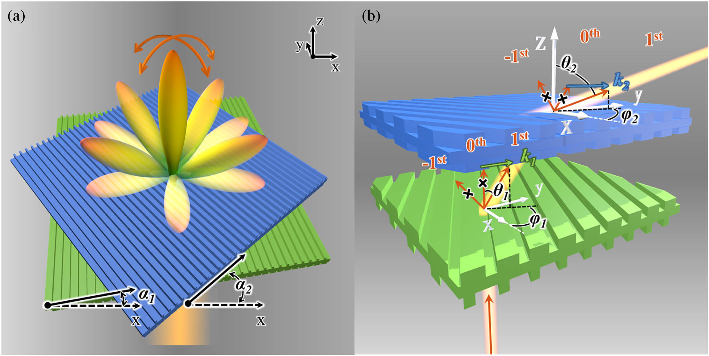
The beam scanner is composed of two metagratings whose orientation angles and can be independently tuned, as shown in Fig. 1(a). The metagratings are uniform along one direction, and periodic along the orthogonal direction. The cross sections of the supercells are carefully designed to suppress diffraction in all the opening orders except the first order. This is equivalent to sequentially offering tangential wave vectors and (bold font for vectors and non-bold font for scalars) with tunable in-plane direction and fixed magnitude to the incoming beam. As shown in Fig. 1(b), the normally incident beam is diffracted to (, ) by adding the vector from the bottom metagrating and to (, ) by the contribution of from the top metagrating through suppressing diffraction in unwanted orders. Separation of the two metagratings in Fig. 1(b) is for clarity of beam propagation. In fact, they are placed in close proximity to avoid walkoff.
Figure 1.(a) Schematic of the metagrating pair for omnidirectional beam steering through in-plane rotation. The orientation angles of each metagrating and are defined between the grating wave vector and the global axis. (b) Details of the beam propagation through dual diffraction engineering.
Vector summation of and is schematically illustrated in Fig. 2(a). When the bottom metagrating is oriented towards with fixed , rotation of the top metagrating sweeps the total tangential wave vector along the dark yellow circle passing through the origin and centered around the tip of . The steered beam travels in a cone centered around the direction in which the beam would have been steered by the bottom metagrating alone, as shown by the inset of Fig. 2(a). Further change of means revolution of this cone around the optical axis indicated by light yellow circles. The beam directions (, ) and (, ) are related to the two wave vectors by
Figure 2.(a), (b) Beam steering scheme using wave vector operation. The trajectory of the composed is given by fixing and rotating when the wave vector length is in (a) and in (b). The trajectory is given by the dark yellow curves for and light yellow curves when , 180°, and 270°. The gray region in (b) shows the cases when the composed is longer than , where the top metagrating offers a for beam steering. (c)–(f) Relation of the beam direction (, ) with the orientation angles and when is [(c), (e)] and [(d), (f)].
For simplicity, we set the same period to the two metagratings, and the tangential wave vectors have the same magnitude . The choice of or determines the maximum steering elevation angle as when . The minimum elevation angle is when . in Fig. 2(a) is , and the elevation angle covers 58° when the top metagrating is rotated relative to the bottom one. The critical for omnidirectional steering is , corresponding to a 30° diffraction angle of each metagrating. By setting larger than , the beam can be directed towards any direction in the entire half space. Figure 2(b) shows the vector summation when , corresponding to a 50° diffraction angle of the metagrating. Fixing to be 0°, rotation of from 100° to 180° leads to wave vector scan along the dark yellow arc, where the elevation angle covers 90°. According to Eqs. (3)–(5), the rotation range of relative to to tune the elevation angle from minimum to maximum (named ) is related to by if . So a large wave vector not only ensures omnidirectional coverage, but also narrows down the in-plane rotation range. In general, we can define the beam steering speed as the derivative of the beam angle swept with respect to time given the rotation speed and initial orientation of the two metagratings. Detailed derivation of the speed can be found in Appendix A. Besides assigning a higher rotation speed to each layer, large-angle diffractive metagratings with long wave vectors help to enhance the beam steering agility.
In Fig. 2(b), when is out of [100°, 260°], will be larger than , leading to evanescent diffraction. This produces a large scan gap. If one intentionally tailors the diffraction within the gap, it is possible to redirect the beam into the real space. For example, when falls in the gray sector, the top metagrating offers a negative wave vector (st order), and the vector sum will be folded into the dark yellow arc again. This requires the top metagrating to have incident azimuth angle -dependent diffraction into the st order or st order if the structure is fixed (in other words, orientation angle -dependent diffraction if the incident beam is fixed). So, the wave vector is not only rotatable but also reversible, so as to form an obtuse angle with to ensure effective beamforming above the light line.
Figures 2(c)–2(f) show the variation of the elevation angle and azimuth angle of the beam when small-angle and large-angle diffractive metagratings are oriented towards different directions. The maximum elevation angle is 58° in Fig. 2(c) and 90° in Fig. 2(d), indicating omnidirectional steering in the latter case. For all the possible orientation pairs (, ), the beam is steered twice and four times across the entire field of view by the small-angle metagrating and the large-angle metagrating, respectively. In Figs. 2(d) and 2(f), the region enclosed by the solid line is the contribution of the st-order diffraction in both layers, while the region enclosed by the dashed line is the contribution of the st-order diffraction in the bottom and the st-order diffraction in the top. As a result, one can take full advantage of one round rotation for beam steering with double steering speed.
3. INVERSE DESIGN OF DIFFRACTIVE METAGRATINGS
With the target diffraction performance in hand, we next design the supercell of each metagrating using the target-driven inverse optimization, which has been proven as an effective tool for complex optical design [24,26–28]. The metagrating is made of polylactic acid (PLA) with refractive index of 1.57 around the target operation frequency 0.14 THz, which can be rapidly prototyped by three-dimensional (3D) printing. Considering the low refractive index, each metagrating has a bilayer configuration to increase the diffraction flexibility, which has been successfully used for static large-angle beam deflection in our previous study [25,29]. The cross section simply contains a single ridge on each side of the dielectric spacer over a period. According to the discussion in Fig. 2(b), the period is set as in the two metagratings to offer an effective grating vector of in the st order.
The bottom metagrating is designed for blazed diffraction towards the st order with normal excitation while suppressing other orders, and such diffraction should be polarization-insensitive to avoid fluctuation during rotation. For this goal, we align the right edge of the ridges to break the structure symmetry, and optimize the geometric parameters denoted in Fig. 3(a) by maximizing the objective function using the gradient descent optimization algorithm, where is the th-order diffraction efficiency when the bottom metagrating is oriented along . The incident beam is linearly polarized along . Although the metagrating is an anisotropic structure, the optimization by considering orthogonal orientation angles ensures the polarization insensitivity of the diffraction. The optimization is quickly converged, since the simulation and evaluation of a single 2D supercell with in-plane periodicity consume negligible time. Figure 3(b) is the cross-section picture of the 3D printed bottom metagrating. The optimized st-order efficiency is above 90% in Fig. 3(c) regardless of the orientation angle . Physical explanation of the diffraction suppression in the zeroth and st orders can be found through modal analysis in our previous study [25]. The measured intensity distribution of the bottom metagrating towards different directions is shown in Fig. 3(d). The st order is dominate, and other orders are suppressed. The measured st-order diffraction efficiency is 86% by dividing the power in the main lobe over the incident beam power, which is marked in Fig. 3(c) at for comparison with the simulation result.
Figure 3.Characterization of individual metagratings. (a) Schematic cross section of the bottom metagrating. (b) Photograph of the 3D printed bottom sample. (c) Simulated diffraction efficiency of each order when the bottom metagrating has different orientation angles. (d) Measured angular distribution of the intensity at . (e) Schematic cross section of the top metagrating with mirror symmetry. (f) Photograph of the 3D printed top sample. (g) Simulated diffraction efficiency of the top metagrating at different orientation directions with incident angle of 50°. (h) Measured intensity distribution for 50°excitation when is set to 0° and 180°. The insets of (d) and (h) show the configuration of the metagrating relative to the incident beam in experiment. Stars in (c) and (g) are the measured first-order efficiency. (i) Experimental setup. (j) Details of the two metagratings mounted on rotatable support.
The diffracted beam of the bottom metagrating becomes the incident beam of the top one, which is in an off-normal direction. Previous study uses the same design for top and bottom layers, as the beam deflection by a single layer is not strong. Here the top metagrating is separately designed as the beam is bent by 50° after the bottom layer. To offer -dependent st-order diffraction, we add mirror symmetry to the top metagrating with respect to the dashed line in Fig. 3(e). Once the left half geometry for st-order diffraction is found, the flipped right half geometry will offer the st-order diffraction when the incident beam direction is flipped as well.
Geometric parameters are optimized in the same way as that of the bottom metagrating but using oblique incidence (, ). The objective function to be maximized is Here three orientation angles are selected from the pink sector of Fig. 2(b). The optimized bottom metagrating is 3D printed in Fig. 3(f). The diffraction efficiency for this metagrating is shown in Fig. 3(g). The st order is dominant when is from 107° to 180°. The st order is dominant when is from 0° to 73°. The st- and st-order responses are symmetric due to the structure symmetry, which meet the switchable diffraction requirement for the top metagrating in Fig. 2(b). The maximum st-order diffraction efficiency is 81% around and 132°. When is around 0° or 180°, the appearance of the order reduces the st-order efficiency to some extent. There is a small region around where the dominant order becomes the zeroth order (two metagratings are orthogonally oriented). In this case, the top metagrating loses tuning capability and the beam is steered by the bottom metagrating only.
For experimental characterization of the top metagrating, it is tilted by or . The measured main beam in Fig. 3(h) is always normal to the metagrating surface according to the st-order and st-order diffraction, respectively. A relatively large side lobe in the zeroth order is observed, which is consistent with the simulation result at and in Fig. 3(g). The simulated and measured st-order diffraction efficiencies there are 49% and 46%, respectively.
Figure 3(i) is the setup to test each of them and the cascading of them. The radiation from an IMPATT diode at 0.14 THz is collimated by an HDPE lens before launching to the metagrating. A half wave plate is inserted to tune the polarization if needed. The size of the metagrating is , which is large enough to avoid the illumination leakage. The diffracted beam is measured by mounting the detector on an angle-resolved rotation stage. The angular distribution is centered around the surface normal () in the horizontal plane. A close look of the cascaded metagratings mounted on rotatable frames is shown in Fig. 3(j). Fabrication details of the metagratings can be found in Ref. [30]. The dimensions of all the metagratings throughout the study are provided in Table 1.
Dimensions of the Metagratings (unit: mm)
Metagratings
Period
One-beam bottom metagrating
2.80
2.12
3.51
3.18
1.63
0.64
Dual-beam bottom metagrating
2.00
3.70
3.30
0.69
1.37
Top metagrating
2.32
2.24
1.57
0.82
2.56
4. EXPERIMENT OF OMNIDIRECTIONAL BEAM STEERING
To test the beam steering capability, we mount two metagratings on a hollow rotation support, and independently tune the orientation of each one. We set the two metagratings oppositely oriented with and for the first measurement, and rotate them in opposite directions for the following cases, as noted in Fig. 4(a). The steered beam shows a fixed azimuth angle and tunable elevation angle from 0° to 77°. The angular distribution is measured by rotating the detector around the metagratings at a radial distance of 30 cm. The maximum elevation angle of 77° corresponding to a solid angle of is a significant extension of the beam steering range, which is only limited by the sheltering of the rotation support, and can potentially approach 90°.
Figure 4.Single-beam steering with variable elevation angles. (a) Measured angular distribution of the beam intensity when the two metagratings have orientation angles as marked by the insets. (b) Measured intensity profile when the steered beam is focused by a metalens. (c) Simulated far-field diffraction pattern when the two metagratings have the same orientation angles as that in (a).
To better visualize the steered beam in 3D space, a metalens with high numerical aperture of 0.94 is added after the metagratings to focus the steered beam into a small cone, and the detector is mounted on a 3D translation stage to detect the intensity distribution in the focal plane of the metalens. The details of the metalens can be found in Ref. [24]. The measured intensity profiles are summarized in Fig. 4(b). It is observed that the spot is gradually deviated from the optical axis as the two metagratings are rotated in opposite directions. The spot deviation from the center is calculated in advance as a function of the incident angle in Appendix B. Here we translate the spatial deviation in the focal plane into the elevation angle of the incoming beam of the metalens, as marked in the top axis of Fig. 4(b). In addition, full-wave simulated far-field diffraction patterns of the metagrating pair are given in Fig. 4(c). The steered beam direction shows good agreement over a spherical arc, in the focal plane, and in the simulated far field. Besides the main beam, a weak stray beam is observable in some cases, which is in the st order of the bottom metagrating and the zeroth order of the top metagrating. The appearance of the stray beam is due to the less efficient st-order diffraction of the top metagrating in Fig. 3(g). In addition, the long shadow around the main beam spot for , in Fig. 4(b) is due to the strong comatic aberration of the metalens (Appendix B).
To steer the beam with fixed elevation angle and variable azimuth angle, we rotate the two metagratings as a whole. Figures 5(a)–5(d) show the intensity distribution when we set an angle difference of to two metagratings and rotate them with 90° steps. The elevation angle is fixed as 60°. The azimuth angle covers complete 360° when the whole device rotates a round. Figures 5(e)–5(h) show the simulated far-field patterns, which agree well with the measured intensity distribution in terms of the main beam and even the undesired side lobes. So the field of view covers a 77° elevation angle and 360° azimuth angle, over which the resolvable beam spot reaches 660 according to the measured beam width in Fig. 4(a).
Figure 5.Single-beam steering with variable azimuth angles. (a)–(d) Measured intensity profile when the two metagratings are rotated as a whole. The orientation angles are marked in the insets with a fixed angle difference of 110°. (e)–(h) Simulated far-field diffraction patterns.
To find the beam steering efficiency, we calculate the ratio of the power in the main beam to the input power. Figure 6(a) summarizes the simulated and measured efficiency when the beam is bent to different elevation angles. The efficiency is maximum around 60°, 69% being in simulation and 59% in experiment. The average efficiency is 56.6% and 41.4% in simulation and experiment, respectively. We attribute this discrepancy to the dimension error of the 3D printed samples. In contrast, if the two metagratings have identical structure without considering the oblique incidence to the top layer, the simulated overall efficiency is only around 10% (Appendix C). This proves the neccesity of separate design of each metagrating for efficient beam steering.
Figure 6.(a) Simulated and experimentally realized beam steering efficiency when the beam is directed to different elevation angles. (b) Intensity distribution and efficiency for single-beam steering at different frequencies besides the designed 0.14 THz.
All the results in the main text are obtained at 0.14 THz. We theoretically study the operation bandwidth of the metagrating pair for single-beam steering. We choose a specific set of orientation angles (, ), and study the beam direction and efficiency variation with frequency. The results are shown in Fig. 6(b). The elevation angle decreases with frequency. The efficiency is maximum at 0.14 THz, and reduces for lower or higher frequencies. If the operation bandwidth is defined by limiting the efficiency above 50%, the theoretical bandwidth of the device is from 0.13 THz to 0.16 THz.
5. EXTENSION TO MULTI-BEAM STEERING
Steering multiple beams simultaneously is highly desired to improve the searching and tracking performance and to promote information sharing over a communication network. Following the nonlocal diffractive scheme, one can simply tailor the diffraction pattern of each metagrating to realize diversified multi-beam steering. Figure 7(a) schematically shows the vector composition for dual-beam steering. The bottom metagrating behaves as a beam splitter to offer and simultaneously via the st-order diffraction. The top metagrating is the same as the top one for single-beam steering, which offers and , respectively, for the split beams. When fixing the bottom metagrating () and rotating the top one, two composed vectors are always opposite ( and ) with the vector tips moving along the yellow solid arcs symmetrically, as indicated by the arrows in Fig. 7(a). Rotation of the bottom metagrating will rotate the arc pair around the origin, so that two beams can symmetrically scan over the half space.
Figure 7.Design and characterization for dual-beam steering. (a) Dual-beam steering scheme using vector operation. (b) Bottom metagrating with center-aligned ridges for beam splitting. (c) 3D printed bottom sample. (d) Beam steering in the plane with different elevation angles. The orientation angles and the wave vectors offered by each metagrating are marked by the insets. (e) Measured intensity profile in the focal plane ( plane) of the metalens. (f) Simulated far-field pattern.
The beam splitting bottom metagrating is optimized using the same objective function as Eq. (8). Here we set the supercell to be axially symmetric in Fig. 7(b), which means the top and bottom ridges are center aligned instead of edge aligned. This ensures equal efficiency in the st and st orders under normal excitation. The 3D printed sample is shown in Fig. 7(c). When cascading this splitter with the original top metagraing [in Fig. 3(e)], the measured intensity distributions over a spherical arc and in the focal plane of the metalens are listed in Figs. 7(d) and 7(e). Two beams are symmetrically steered from the center to the edges with the maximum elevation angle of 77°. The orientation and the wave vectors of each layer are marked in the inset of Fig. 7(d). The solid vectors are added together for one beam, and the dashed vectors are added for the other beam. The simulated far-field patterns in Fig. 7(f) show very good agreement with the measured results. For all cases, the two beams have almost the same intensity.
6. CONCLUSION
To summarize, omnidirectional single-beam and multi-beam steering at 0.14 THz is successfully demonstrated by mechanically controlling the in-plane orientation of two metagratings. The top and bottom metagratings composed of simple one-dimensional supercell structures are optimized for efficient large-angle 1st-order diffraction under normal and oblique excitation with polarization independence. Through dual diffraction with rotatable and reversible grating vectors, the beam can be directed into arbitrary direction over field of view with average steering efficiency of 41.4% and possibly high steering speed. The study here with additional merits of compact configuration, low power consumption, large aperture size, and high power endurance yields an efficient and cost-effective platform for versatile beamforming much needed in THz applications.
APPENDIX A: DERIVATION OF THE GENERAL BEAM STEERING SPEED
The beam steering speed is defined as the derivative of the beam angle swept with respect to time, which can be written as where is a tiny time slot, and is the change of the beam direction. As shown in Fig. 8(a), an arbitrary initial angle is set between two metagratings, whose wave vectors and have the same length . The vector sum has a length of . The bottom and top metagratings are rotating at their own speed and . After , and move to and . The angle between and is . The vector sum now has a length of . The angle between the vector sum and is . We next project and to the free-space wave vectors and and calculate the angle between them. can be represented by the vector , and by . The angle between and is obtained from their dot product . Therefore, the speed of beam steering can be calculated by .
Figure 8.(a) Illustration of the steering over a tiny time slot. (b) Variation of the steering speed with the relative initial angle when has different values.
For simplicity, we ignore frictional forces or any other delays caused by mechanical control in current study. If the bottom metagrating is static and the top one gives a moderate rotation speed of , Fig. 8(b) shows the beam steering speed at different initial angle and different wave vector values . If , there is a steering gap when is around 90°, as the dominant diffraction of the top metagrating is in the zeroth order from Fig. 3(g). And due to the mirror symmetry of the top metagrating, the speed is symmetric with respect to . Apparently, higher steering speed is achieved when the metagrating offers a larger wave vector. For in the main text, the steering speed is more than 2700(°)/s. and 100° corresponds to beams along the optical axis and the in-plane direction, so the beam moves faster as it is more deviated from the optical axis.
APPENDIX B: SIMULATION OF THE METALENS WITH OFF-AXIS ILLUMINATION
The metalens used to focus the steered beam is also 3D printed. The design details are reported in Ref. [24], where the performance is characterized for a normally incident beam only. Here we study its response with off-axis illumination, so that one can infer the incoming beam direction based on the position of the spot in the focal plane. Figure 9(a) is the front view of the metalens. The obliquely incident beam with elevation angle of is focused by the metalens. As shown in Fig. 9(b), the intensity distribution is recorded 15 mm after the metalens through FDTD simulation, which is the focal plane for normal incidence. As increases from 0° to 80° in Figs. 9(c)–9(g), the spot in the focal plane gradually deviates from the center, and saturates as the incident angle approaches 90°. The relation between the deviation and the incident angle is plotted in Fig. 9(h), which is a guidance to retrieve the beam direction during the 3D beam steering. In addition, the comatic aberration is apparent around , which gives a tail to the steered beam in Fig. 4(b) of the main text.
Figure 9.Front view of the high numerical aperture metalens for focusing of the steered beam. (b) Illustration of the beam intensity calculation in the focal plane of the metalens with oblique incidence. (c)–(g) Simulated intensity with different incident angles from 0° to 85°. (h) Relation between the deviation and the incident angle .
APPENDIX C: PERFORMANCE OF TWO METAGRATINGS WITH IDENTICAL STRUCTURES
To validate the necessity of separate optimization of the bottom and top metagratings, we characterize the diffraction responses when the two layers are made of identical structures. If the top metagrating is the same as the optimized bottom metagrating in Fig. 3(a), the far-field radiation patterns of the cascaded structures are simulated in Figs. 10(a)–10(e) when they have different in-plane orientation angles as marked by the insets. When the two layers have opposite orientation angles in Fig. 10(a), the main beam is not the one with , but the one with . This means that the dominant diffraction of the top metagrating is the zeroth order instead of the first order, so that the energy is mainly controlled by single diffraction of the bottom metagrating, instead of dual diffraction of the two layers. When the two layers are rotated in opposite directions in Figs. 10(b)–10(e), the main beam is still the one diffracted by the bottom metagrating. The top metagrating loses beam bending capability as the oblique incidence is not taken into the design consideration. As a result, the beam steering efficiencies at different elevation angles are only around 10% in Fig. 10(f), being much lower than that in Fig. 6(a).
Figure 10.(a)–(e) Simulated far-field radiation pattern of cascaded metagratings when the top and bottom metagratings have identical structure and different orientation angles. The arrow points to the target beam. (f) Calculated diffraction efficiency of the target beam at different elevation angles.
[3] X. Yu, T. Miyamoto, K. Obata, Y. Hosoda, J.-Y. Kim, M. Fujita, T. Nagatsuma. Direct terahertz communications with wireless and fiber links. IRMMW-THz, 1-2(2019).
[16] M. Tamagnone, S. Capdevila, A. Lombardo, J. Wu, A. Centeno, A. Zurutuza, A. M. Ionescu, A. C. Ferrari, J. R. Mosig. Graphene reflectarray metasurface for terahertz beam steering and phase modulation(2018).