
Yuefang Yan, Rumao Tao, Yu Liu, Yuwei Li, Haoyu Zhang, Qiuhui Chu, Min Li, Qiang Shu, Xi Feng, Wenhui Huang, Feng Jing. Research progress and prospect of high power all-fiber coherent beam combination based on fiber combining devices[J]. High Power Laser and Particle Beams, 2023, 35(4): 041005
- High Power Laser and Particle Beams
- Vol. 35, Issue 4, 041005 (2023)
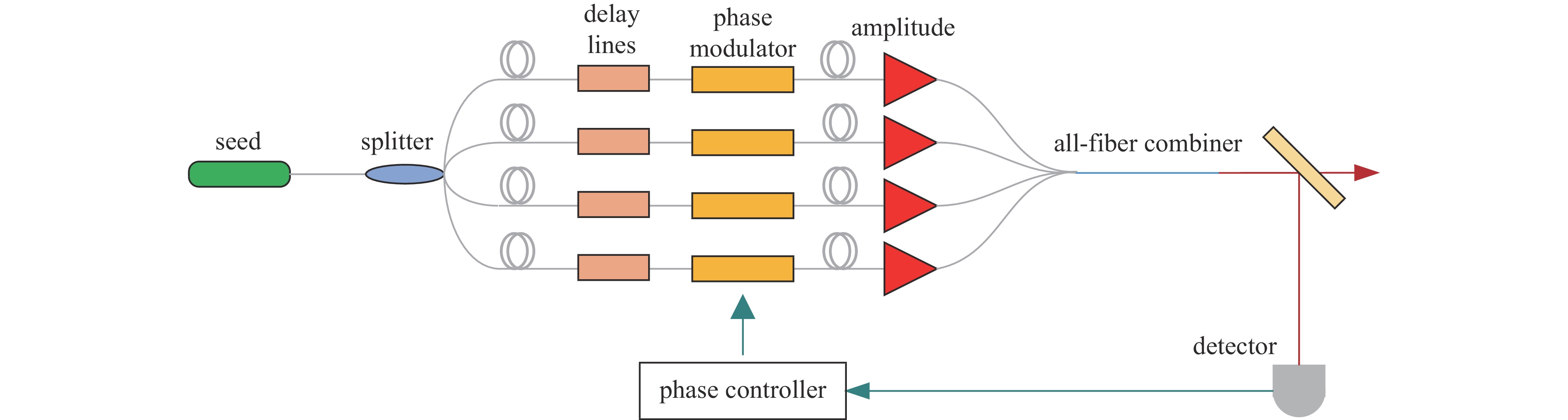
Fig. 1. Schematic diagram of the all-fiber coherent beam combination system

Fig. 2. Diagram of CBC based on optical fiber coupler
Fig. 3. Schematic diagram of two-channel CBC based on fiber polarization beam combiner
Fig. 4. Diagram of the structure of photonic lantern and traditional lantern
Fig. 5. Coherent beam combination principal of photonic lantern
Fig. 6. Schematic diagram of 3×1 photonic lantern coherent combining
Fig. 7. Diagram of the structure and the results of kW photonic lantern system
Fig. 8. Structure and section diagram of 61-core photonic lantern
Fig. 9. Experimental structure diagram and results of 3×1 photonic lantern
Fig. 10. Schematic diagram of the structure of the coherent signal beam combiner based on taper technology
Fig. 11. Diagram of the experiment of coherent signal beam combiner and light spots before and after experiment
Fig. 12. Diagram of the 16 kW coherent beam combination system and the results
Fig. 13. Schematic diagram of the experimental structure of the two-channel Y-shaped coherent beam combination
Fig. 14. Schematic diagram of the beam combining structure of the 4-way beam combiner
Fig. 15. Photograph of the free-space beam combiner module based on self-imaging effect
Fig. 16. Cross section of a rectangular core fiber
Fig. 17. Diagram of structure and results of 2×2 incoherent signal combiner
Fig. 18. Schematic diagram of square fiber combiner
Fig. 19. Diagram of the function of the combining effects of NA with different fiber arrays
Fig. 20. Theoretical and experimental verification results of square fiber self-imaging effect
Fig. 21. Diagram of the beam combiner based on the square fiber, the input spots and combining result
Fig. 22. Cross section of a square core fiber

Set citation alerts for the article
Please enter your email address
© Copyright 2018-2021 | Chinese Laser Press. All Rights Reserved 沪ICP备15018463号-20