• Photonics Research
  • Vol. 10, Issue 8, 1915 (2022)
Hao Ding1, Qizhuang Cen2、3、4, Kun Xu1, Ming Li2、3、4、6, and Yitang Dai1、5、*
Author Affiliations
  • 1State Key Laboratory of Information Photonics and Optical Communications, Beijing University of Posts and Telecommunications, Beijing 100876, China
  • 2State Key Laboratory on Integrated Optoelectronics, Institute of Semiconductors, Chinese Academy of Sciences, Beijing 100083, China
  • 3School of Electronic, Electrical and Communication Engineering, University of Chinese Academy of Sciences, Beijing 100049, China
  • 4Center of Materials Science and Optoelectronics Engineering, University of Chinese Academy of Sciences, Beijing 100190, China
  • 5Peng Cheng Laboratory, Shenzhen 518052, China
  • 6e-mail: ml@semi.ac.cn
  • show less
    DOI: 10.1364/PRJ.461637 Cite this Article Set citation alerts
    Hao Ding, Qizhuang Cen, Kun Xu, Ming Li, Yitang Dai. Observation of parity-time symmetry in time-division multiplexing pulsed optoelectronic oscillators within a single resonator[J]. Photonics Research, 2022, 10(8): 1915 Copy Citation Text show less

    Abstract

    In recent years, parity-time (PT) symmetry in optoelectronic systems has been widely studied, due to its potential applications in lasers, sensors, topological networks, and other fields. In this paper, a time-division multiplexed pulsed optoelectronic oscillator (OEO) is proposed to study the dynamics of a PT symmetry system. Two microwave pulses are used to realize the PT symmetry in a single spatial resonator based on the temporal degrees of freedom. The gain and loss of the microwave pulses and the coupling coefficient between them can then be controlled. We first demonstrate the phase diagram from PT broken to PT symmetry in the OEO system. We theoretically prove that the perturbation of a coupling-induced phase shift larger than (2π)×10-2 causes the disappearance of the PT symmetry. In this experiment, the perturbation is less than (2π)×0.5×10⁻²; thus, the phase transition of PT symmetry is observed. In addition, multipairs of PT-symmetry pulses indicate that pulsed OEO could be used to implement complex non-Hermitian Hamilton systems. Therefore, it is confirmed that pulsed OEO is an excellent platform to explore the dynamics of PT symmetry and other non-Hermitian Hamiltonian systems.

    1. INTRODUCTION

    Since Bender and Boettcher [1] first proved in 1998 that a Hamiltonian commuted with a parity-time (PT) operator has real spectra, PT symmetry has been an active subject of research in physics [27]. This novel conclusion appeared to be counterintuitive, which means that the eigenvalues of non-Hermitian Hamiltonians are real. Another crucial characteristic is the spontaneous symmetry breaking during the phase transition from real to complex in this kind of system [1]. The eigenvalues become complex above the threshold, but the PT symmetry remains intact. Moreover, PT-symmetry systems have many attributes of conservative systems, although they are dissipative. Physically, a PT-symmetry system is unique due to these characteristics. The PT symmetry makes the loss useful, which is very irradiative in physics. In particular, El-Ganainy et al. [8] demonstrated that such complex PT-symmetric systems can be realized within the paraxial refraction approximation by involving the symmetric index and the antisymmetric gain/loss ratios; that is, n(r)=n*(r). They built a PT-symmetry model based on the coupled mode theory, and proposed the concept of PT-symmetry waveguide optics. The model greatly reduces the difficulty to achieve PT symmetry. PT symmetry was soon confirmed in experiments [9,10] and then quickly expanded to other areas of study. It has, for example, been implemented in many systems: waveguides [912], lasers [1317], microcavities [18,19], atomic systems [20,21], diffusive systems [22], and circuit systems [2325]. The PT symmetry opens new possibilities in photonics to generate, manipulate, and transmit light.

    A classical PT-symmetric system consists of two spatially distributed cavities with gain and loss modes. More precisely, two cavities with the same Q factor are required for a system. Some studies have recently focused on implementing a PT-symmetric system with only one spatial cavity. These studies mainly introduce the concept of synthetic dimensions, which substitute spatial dimensions with the system parameters. By introducing synthetic dimensions, there is no need for two cavities with the same Q value. The experiments performed using the system’s parameter dependency as the synthetic dimension comprise the wavelength [26], clockwise (CW) and counterclockwise (CCW) optical modes [16,27,28], and polarization [29]. The PT-symmetry coupling in these structures is limited to two subsystems. Hence, a simple question must be answered: is there a scheme to implement PT-symmetry lattice, non-Hermitian trimer [30] with a single spatial resonator?

    In recent years, crucial experiments have been conducted in the field of optoelectronic oscillators (OEOs) [3134]. OEOs are dissipative nonlinear systems with a closed feedback loop that converts the light energy from the pump laser to the microwave [3537]. Some studies have demonstrated that PT symmetry can improve the side-mode suppression ratio, reduce the signal phase noise, and overcome the mode-selection challenge [32,34,3840]. Simultaneously, OEOs are considered a viable platform to study PT symmetry due to their rich nonlinear and flexible structure [41].

    Here, we report what we believe, to the best of our knowledge, is a novel scheme to achieve PT symmetry within one resonator. A time-division multiplexed (TDM) pulsed OEO, which proves a test platform for generalized PT symmetry in the optoelectronic system, is designed. Each microwave pulse can be considered as an independent oscillator with temporal degrees of freedom. The gain/loss of pulses and the mutual injection coefficient between them are all controlled to achieve PT symmetry. A pulsed OEO paves the way for a new class of PT symmetry implementations with multiple subsystems. In existing OEO systems [3134], the coupling is a “combine-and-split” implementation. Compared to these studies, the phase of the cross-coupling term in the proposed scheme is performed by mutual injection of the oscillation, and it is arbitrarily and independently varied. In OEO, the phase transition of eigenfrequencies of a PT-symmetry OEO is first demonstrated. The frequency-splitting values of PT-symmetric pulses are measured and a comparison of even gain microwave pulse is conducted. The experimental results follow the theoretical prediction. Through the link delay control, the arbitrary coupling-induced phase shift can be set and the error can be kept within (2π)×0.5×10². In addition, multiple PT symmetry coupled microwave pulses are obtained in a single cavity. We believe that the microwave pulses in a pulsed OEO can be referred to as the carrier for more complex non-Hermitian Hamilton systems.

    2. PRINCIPLE OF A PT-SYMMETRY PULSED OEO IN A SINGLE RESONATOR

    The schematic diagram of a PT-symmetric pulsed OEO based on TDM is shown in Fig. 1(a). In contrast to a traditional OEO, a pulsed OEO uses an optical pulse train with a period of cavity delay Tc as the laser source, rather than continuous light. Each optical pulse causes a microwave pulse to oscillate in turn. Tc is also the period of the microwave pulse. Two microwave pulses with a Tpulse time interval are used as the subsystems of PT symmetry. The gain and loss of microwave pulses are balanced, and the pulses are coupled at the coupling part.

    Principle of TDM pulsed OEO to realize PT symmetry. (a) Scheme diagram of the PT-symmetry pulsed OEO. (b) Frequency splitting of the PT-symmetric supermodes, where fS is the longitudinal mode spacing and κEP is the exception point.

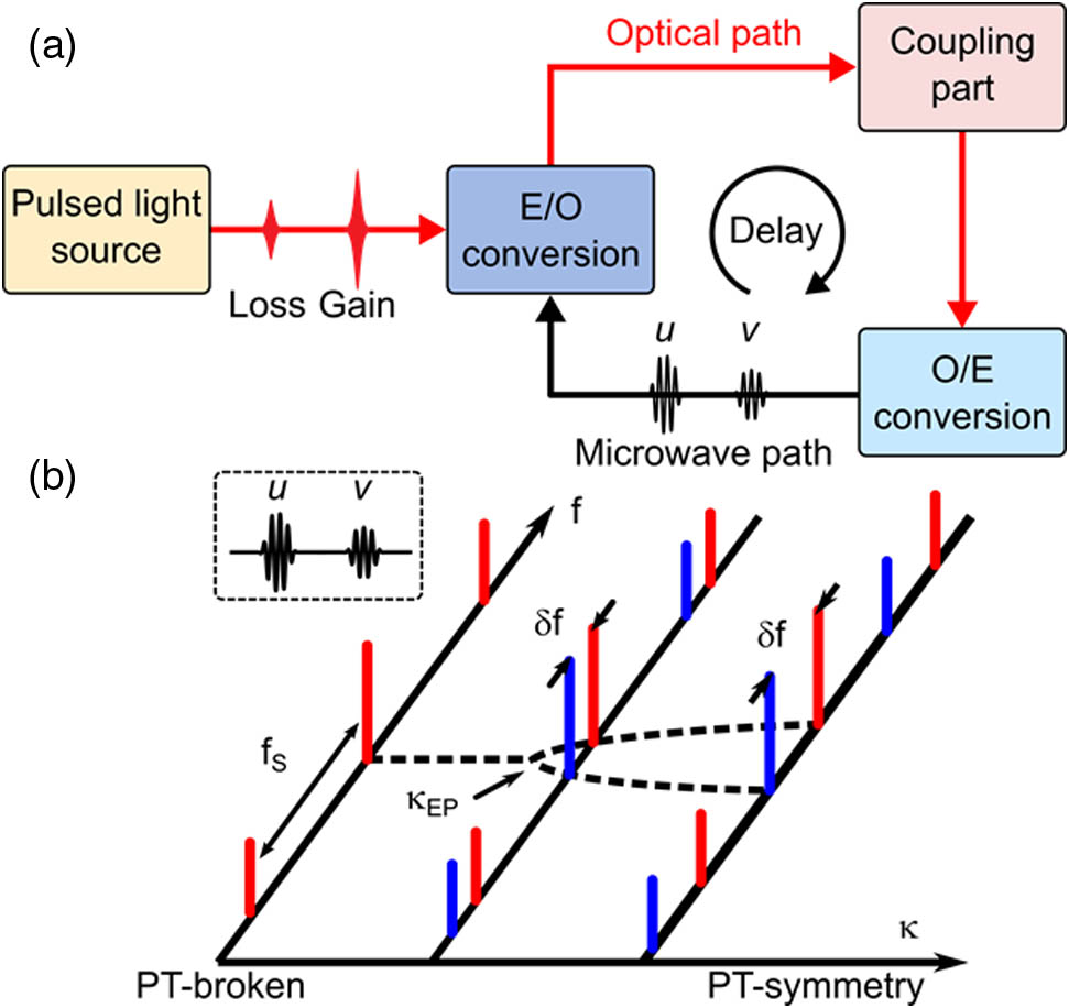
    Figure 1.Principle of TDM pulsed OEO to realize PT symmetry. (a) Scheme diagram of the PT-symmetry pulsed OEO. (b) Frequency splitting of the PT-symmetric supermodes, where fS is the longitudinal mode spacing and κEP is the exception point.

    Since group velocity dispersion is ignored in the setup, the microwave pulses are completely represented by a single complex amplitude. The PT-symmetric microwave pulses are denoted by u and v. The interaction of PT-symmetric microwave pulses satisfies the dynamic equations [42] ddt(uv)=(iω0+γuκexp(iθv)κexp(iθu)iω0+γv)(uv),where t is the slow time scale, ω0 is the angular frequency of microwave pulses without coupling, γu and γv are the gain (loss) ratios of the microwave pulses, κ is the mutual injection coefficient between the microwave pulses, and θu and θv are the phase shift introduced by the injection of the coupling part.

    Based on Eq. (1), the eigenfrequencies of supermodes of the system are given by ω±=ω0iγu+γv2±exp[i(θu+θv)]κ2(γuγv2)2.

    When the PT-symmetry condition is satisfied (i.e., γu=γv=γ and θu=θv=π/2), the eigenfrequencies are simplified as ω±=ω0±κ2γ2.

    Figure 1(b) presents the coupling coefficient κ versus the frequency spectrum for the PT-symmetric microwave pulses. Because the microwave pulses involved in coupling have a period of Tc, the frequency spectrum of the coupled pulses is discrete and the frequency spacing is fS=1/Tc. The carrier frequency of microwave pulses is the real part of the eigenfrequencies of the two supermodes. Thus, the focus is on the region around ω0. The real part of the eigenfrequencies in Eq. (3) from PT broken to PT symmetric is highlighted by the black dashed line in Fig. 1(b). PT symmetry breaking occurs if κ<γ. ω± are a pair of complex conjugate numbers. The supermodes degenerate, and the oscillation corresponding to ω± increases (or decreases) exponentially. κEP=γ is the threshold, referred to as the exception point (EP), where the system undergoes a phase transition. If κ>γ, the system is PT symmetric and has real eigenfrequencies. The difference between eigenfrequencies and ω0 is ±κ2γ2.

    3. EXPERIMENTS AND RESULTS

    The detailed setup of the time-delay feedback PT-symmetric OEO is shown in Fig. 2(a). The multiwavelength laser is used to perform the coupling of the microwave pulses. The continuous light of three wavelengths is combined at the wavelength division multiplexer (WDM1), and modulated into the optical pulse train using the Mach–Zehnder modulator (MZM1). The normalized power transmission β is controlled by the modulation signal, which is generated by an arbitrary waveform generator (AWG). MZM1 is set to the minimum transmission point to suppress the unexpected pulses. The typical suppression ratio is at least 30  dB. The optical pulse train is injected into a 92 m fiber by the MZM2 and coupled at the coupling part, which consists of WDM2, WDM3, a delay fiber, and optical delay lines (ODLs). The optical pulses are converted into microwave pulses at a photodetector (PD). The microwave pulses are amplified by an electrical amplifier (EA) to compensate for the link loss. They pass through the bandpass filter (BPF) with a center frequency of 10 GHz and a bandwidth of 4 GHz to limit the spectrum range. The output is divided into two parts using a 3 dB power splitter. A total of 50% is sent to the oscilloscope, and the rest is injected into the modulation port of MZM2 as a feedback signal.

    Detailed experimental setup of the pulsed OEO. (a) Proposed PT symmetry in time-multiplexed delay systems within a single oscillator. MZM, Mach–Zehnder modulator; WDM, wavelength-division multiplexer; SMF, single-mode fiber; EA, electronic amplifier; BPF, bandpass filter; PD, photonic detector. (b) Microwave pulses (black line) in the cavity and optical pulses generated by the light source. (c) Coupled pulses after the coupling part and the microwave pulses received by the PD (black lines).

    Figure 2.Detailed experimental setup of the pulsed OEO. (a) Proposed PT symmetry in time-multiplexed delay systems within a single oscillator. MZM, Mach–Zehnder modulator; WDM, wavelength-division multiplexer; SMF, single-mode fiber; EA, electronic amplifier; BPF, bandpass filter; PD, photonic detector. (b) Microwave pulses (black line) in the cavity and optical pulses generated by the light source. (c) Coupled pulses after the coupling part and the microwave pulses received by the PD (black lines).

    The coupling of microwave pulses is achieved by three channels at the coupling part. CH2 is used to balance the gain and loss of the microwave pulses. CH1 and CH3 are used to achieve mutual injection between the pulses. CH2 corresponds to the direct-pass path. The gain ratio of the pulse u is controlled by the power of CH2, P2, and the normalized power transmission βu, as shown in Fig. 2(b). Similarly, the gain ratio of the pulse v is controlled by P2 and βv. The balance of gain and loss γu=γv=γ indicates that the net gain of the pulse u is equal to the net loss of the pulse v (i.e., P2βuI0=I0P2βv), where I0 is the threshold optical power of the OEO oscillation without the PT-symmetric coupling. More details are provided in Appendix B.

    The cross-coupling path is achieved by CH1 and CH3. The mutual injection coefficients are proportional to the optical power of CH1 and CH3, and P1 and P3. The mutual injection coefficients of two microwave pulses are equalized by setting P1βu=P3βv. More details are available in Appendix B. The path of CH1 is behind that of CH2 by Tpulse, and the injection from pulse u to pulse v is performed, as shown in Fig. 2(c). The path of CH3 is earlier than that of CH2 by Tpulse, and the injection from pulse v to pulse u is performed. The phase shift between the cross-coupling path and the direct-pass path is achieved by fine-tuning the ODLs at CH1 and CH3.

    The delay of ODL and the phase of the microwave coupling term have a relationship: θu,v=Tu,vω0, where Tu,v is the delay induced by the ODL at the cross-coupling path. The delay of three channels satisfies the relationships T1T2=Tpulse+Tu and T3T2=Tpulse+Tv. In the setup, the carrier of the microwave pulses is approximately 10 GHz, and thus a 25 ps time delay of Tu,v is equivalent to a π/2 phase shift of the pulses.

    The temporally combined optical pulses reach the PD, and are then down-converted to microwave signals by the PD detection. The carrier wavelength of the microwave pulses is much smaller than the pulse width of them. The pulses are approximated as the sine wave signal. Since only the first-order harmonics are preserved, MZM and PD do not introduce additional phase shifts [42]; the coupling phase is naturally introduced just by the delay of the ODL. The signals after PD detection are considered as the superposition of two sine waves with a phase shift. The PD detection produces four microwave pulses, as shown in Fig. 2(c). Only the pulses u and v involved in the PT symmetry are aligned with the optical pulses, and are modulated into the optical domain. The remaining pulses have no corresponding optical pulses, and therefore are all suppressed. Three pairs of PT-symmetric microwave pulses are realized in the same cavity. When the OEO reaches the steady state, the time domain waveform of each pair of microwave pulses is obtained by processing the oscilloscope data at the computer. Finally, the spectrum of each pair of microwave pulses is obtained by Fourier transform.

    The experiments are set up according to Fig. 2 to study the phase transition of PT symmetry, and 1551.72 nm, 1550.92 nm, and 1550.12 nm single-frequency light is used as the optical carrier of CH1–CH3. The spacing between the three wavelengths is 0.8 nm (100  GHz), which exceeds the detection bandwidth of the PD. As a result, the beat of the two-color signals and the power fluctuation induced by the coherence of the optical signal are suppressed. A 508-ns Gaussian pulse train is used as the modulation signal of the MZM1. The coupled microwave pulses have a 21-ns time interval. The delays of the three wavelengths differ by 21 ns, to ensure that the optical pulses of different wavelengths are aligned. The ODLs are tuned to introduce a π/2 phase shift between the cross-coupling path and the direct-pass path. Three pairs of optical pulses are generated by the modulation signal, as shown in Fig. 2(a), and they excite three pairs of PT-symmetric microwave pulses in the cavity.

    CH1 and CH3 are first turned off, and CH2 is turned on. The amplitudes of the modulation pulses are set to be equal to the half-wave voltage of MZM1. The transmittance of MZM1 is the largest (i.e., βu=βv=1). P2 is increased to make the microwave pulses oscillate. The threshold of the optical power is measured to be I0=14.18  dBm. Afterward, CH1 and CH3 are turned on. P2=14.75  dBm, βu=1 and βv=0.75 are kept unchanged. In this scenario, the net gain (loss) of the microwave pulses u and v is balanced, and the PT symmetry is achieved in the system. By increasing P1 and P3, the coupling strength κ/κEP between the microwave pulses increases.

    Figure 3 shows the spectra of three pairs of microwave pulses at the PT-broken state and PT-symmetry state. The spectral line interval is 1.97 MHz, corresponding to the cavity length of 105.0 m. The power of the pulse spectrum is only affected by the saturation power of the oscillation, independent of the net gain ratios of supermodes. The gain/loss ratios of the supermode affect the frequency component of the microwave pulses at the steady state [25]. Therefore, the power of the three groups of PT-symmetric microwave pulses is almost the same when the system is at the PT-symmetry breaking state and PT-symmetry state, respectively. In theory, at the PT-symmetry state, two supermodes simultaneously arise in Fig. 3(b). However, mode competition exists in the stable oscillation OEO in practice. Consequently, only one eigenfrequency is usually seen in the spectrum of each pair of pulses, as shown in Fig. 3(b).

    Spectrum of pulse OEOs with a span of 20 MHz: (a) PT-broken state; (b) PT-symmetry state.

    Figure 3.Spectrum of pulse OEOs with a span of 20 MHz: (a) PT-broken state; (b) PT-symmetry state.

    Figure 4(a) presents the experimental and theoretical results of the frequency detuning of PT-symmetric microwave pulses. When κ<κEP, the frequency lines have no detuning. When κ>κEP, the frequency detuning resembles a hyperbola, which is coherent with the theory. The eigenfrequency changes from degenerate to split with κ/κEP increasing. This indicates that the PT-symmetric microwave pulses evolve from the PT broken state to PT-symmetry state.

    Experiment of PT-symmetry pulsed OEOs. (a) Experimentally and theoretically obtained frequency detuning of the pulses, function of the coupling strength κ/κEP. (b)–(d) Spectrum of three groups of PT-symmetric microwave pulses with the coupled strength marked in (a) with a span of 160 MHz and a frequency resolution of 1 kHz.

    Figure 4.Experiment of PT-symmetry pulsed OEOs. (a) Experimentally and theoretically obtained frequency detuning of the pulses, function of the coupling strength κ/κEP. (b)–(d) Spectrum of three groups of PT-symmetric microwave pulses with the coupled strength marked in (a) with a span of 160 MHz and a frequency resolution of 1 kHz.

    Figures 4(b)–4(d) show the spectrum details of PT-symmetric microwave pulses marked in Fig. 4(b). The span is set to 160 kHz. In Fig. 4(b), P1=4.97  dBm and P3=6.22  dBm, and κ/κEP=0.86 is obtained. For more details, see Appendix B. The pulses are PT broken. The spectra of three pairs of pulses overlap. Afterward, P1 and P3 are increased by 1.80 dBm and κ/κEP=1.30 is obtained. After the threshold value is exceeded, the condition of PT breaking is no longer satisfied. Multiple supermodes emerge in Fig. 4(c). The difference between the eigenfrequencies is 72.1 kHz. The splitting of the eigenfrequencies is 143.7 kHz by further increasing κ/κEP=1.87, as shown in Fig. 4(d). At the data points for 1<κ/κEP<1.15, only a single oscillation peak with frequency detuning is observed. The phenomenon in OEO is the same as that in the laser system. Only one oscillation mode between two degenerate supermodes is observed because of the mode competition [43,44]. We do not determine that the offset frequency is only introduced by the coupling terms; thus, these data points are not shown in Fig. 4(a). It is caused by the limitation of the regulation accuracy of the ODL, which is explained in Section 4.

    Microwave pulses with even gain are also built for comparison. The coupled pulses have the same gain ratios. P2=14.75  dBm, P1=P3, and βu=βv=1 are set. The power of the optical pulse is larger than I0 (i.e., γu=γv=γ>0). According to Eq. (2), the real parts of eigenfrequencies are always different. The difference values are related to the coupling coefficient: δω=ω+ω=2κ. In this condition, even if the coupling strength is very weak, two supermodes are always split.

    Figure 5(a) presents the experimental and theoretical values of frequency detuning of the microwave pulses with even gain. The measurements of frequency detuning are approximated on two straight lines. Compared to Fig. 4(a), the curves of the frequency detuning of these microwave pulses have no intersection. When κ/κEP increases, the frequency split between the two supermodes becomes larger, and the eigenfrequencies have no phase transition. Figures 5(b)–5(d) show the details of the spectrum marked in Fig. 5(a). The power of the cross-coupling path is 5.0 dBm, 6.6 dBm, and 8.0 dBm. The coupling strength is 0.86, 1.24, and 1.72, respectively. The corresponding frequency splitting values are 76.1 kHz, 106.1 kHz, and 152.8 kHz. When the coupling strength increases, the carrier wave of microwave pulses gradually moves away.

    Experiment of even gain pulsed OEOs. (a) Experimentally and theoretically obtained frequency detuning of the pulses, function of the coupling strength κ/κEP. (b)–(d) Spectrum of three groups of even gain microwave pulses with the coupled strength marked in (a) with a span of 160 MHz and a frequency resolution of 1 kHz.

    Figure 5.Experiment of even gain pulsed OEOs. (a) Experimentally and theoretically obtained frequency detuning of the pulses, function of the coupling strength κ/κEP. (b)–(d) Spectrum of three groups of even gain microwave pulses with the coupled strength marked in (a) with a span of 160 MHz and a frequency resolution of 1 kHz.

    4. DISCUSSION

    Through theoretical analysis [45], it is deduced that a π/2 phase shift between the direct-pass path and cross-coupling path determines the emergence of the real eigenfrequencies and the EP. At the condition of PT symmetry, the perturbation of the phase shift δθ is introduced into the Hamiltonian of the system. Equation (1) is then rewritten as (iω0+γκexp[i(π2+δθ)]κexp[i(π2+δθ)]iω0γ).

    The eigenfrequencies of the supermodes are expressed as ω±=ω0±κ2e2iδθγ2.

    Because ω±(δθ)=ω±*(δθ), the sign of δθ does not affect the detuning of eigenfrequencies. Therefore, the situation of δθ>0 is only analyzed. When δθ=0, the system has no perturbation and is PT symmetric. When δθ(0,π/2), two supermodes have complex eigenfrequencies. The curve of κ versus Re(ω±) and Im(ω±) is provided by numerical calculation. According to the experimental parameters, κEP=γ=0.14 and δθ=(2π)·{101,102,103,0} are set. The simulation curves of eigenfrequencies under different perturbations are shown in Fig. 6.

    Numerical simulation of the disappearance of PT symmetry with phase perturbation. (a) Real parts of the eigenvalues for PT symmetry with different δθ. (b) Imaginary parts of the eigenvalues for PT symmetry with δθ.

    Figure 6.Numerical simulation of the disappearance of PT symmetry with phase perturbation. (a) Real parts of the eigenvalues for PT symmetry with different δθ. (b) Imaginary parts of the eigenvalues for PT symmetry with δθ.

    Figure 6(a) presents the real part of the eigenfrequencies Re(ω±), which is the detuning value of carrier frequency of microwave pulses. Figure 6(b) shows the imaginary part of eigenfrequencies Im(ω±), which represents the net gain (loss) ratio of the pulses. When κ<κEP, if no perturbation occurs, Re(ω±) is degenerate and two supermodes amplify and decay, respectively. Only one supermode is observed at the stable oscillation. If the phase shift deviates by π/2, the eigenfrequencies split. The amplifying and decaying supermodes still hold. Only one supermode is also observed. However, the frequencies are offset from ω0. When κ>κEP, if no perturbation occurs, two supermodes have the same net gain and different Re(ω±). Two supermodes are observed at the stable oscillation. If the phase shift deviates by π/2, the gains of the two supermodes are still greater than 0 and less than 0, respectively. Thus, only a supermode is observed in this case. Because of the phase shift perturbation, the coupled system oscillates with only one supermode and the EP disappears.

    In general, the π/2 phase shift of the cross-coupling path plays a crucial role in maintaining a perfect PT symmetry. ODLs are used to tune the coupling-induced phase shift. In addition, the accuracy of ODLs is 0.1 mm, which is equivalent to (2π)×0.5×10². The phase perturbation is small enough to observe the phenomenon of PT symmetry in the presented setup. However, it can be seen from Fig. 6(a) that the measurement near EP requires a smaller phase perturbation that is difficult to achieve with ODL. In an ideal PT-symmetry system, the cross-coupling is purely imaginary. In practice, the real part of the cross-coupling can lead to EP degeneracy [45]. The net gain of one of the supermodes is under the threshold, as shown in Fig. 6(b). Mode competition of the oscillators results in only one supermode being observed. However, the singularity of EP can be restored if the amplification and absorption of the two subsystems are properly designed [4547]. Thus, improving the performance by compensating for gain and loss in the proposed scheme is a good question that should be further studied.

    5. CONCLUSION

    This paper illustrated a TDM-pulsed OEO to perform PT symmetry. The gain and loss of microwave pulses in a single resonator are independently controlled at the direct-pass path, and pulses are coupled by mutual injection at the cross-coupling path. The phase transition curve of PT symmetry is first shown in the OEO system. Compared to the existing OEO, the spectrum details of the frequency splitting are provided. The frequency detuning in the PT-symmetric microwave pulses and the microwave pulses with even gain is also compared. The experimental results are coherent with the theory. Finally, the importance of the π/2 phase shift in the PT-symmetry constraint by Eq. (5) is demonstrated. The phase perturbation can be kept within (2π)×0.5×10², which ensures the bifurcation observed in the experiment. We believe that pulsed OEO has a certain potential in the interdisciplinary studies of optoelectronics and physics. Pulsed OEO will be a research platform used for cluster synchronization, chimera state [48], exotic state [49], and other network dynamics.

    APPENDIX A: PT SYMMETRY IN THE COUPLED PULSED OEO

    In the proposed PT-symmetry OEO, the cross-coupling of the two subsystems is implemented by mutual injection. The coupling process is referred to as an active microwave coupler, as shown in Fig. 7. By tuning the ODL at the cross path in Fig. 7, the values of the coupling-induced phase shift θu and θv are arbitrarily and independently adjusted. The signals in the two subsystems are denoted by u(t) and v(t). The coupling equation is given by (uoutvout)=(tuKexp(iθv)Kexp(iθu)tv)(uinvin),where tu and tv are the net gain of the direct-pass path, K is the injection coefficient of the cross-coupling path, θu and θv are the phase shift introduced by the ODL. Assuming the equivalent loss of the cavity is α, the transfer function of the open loop of the setup is given by (u(t+T)v(t+T))=(αtuαKexp(iθv)αKexp(iθu)αtv)(u(t)v(t)),where T is the delay of the round trip. Near the steady state, u(t) and v(t) vary on a slow time scale. The following approximation can be used: ddt(uv)=1T(u(t+T)u(t)v(t+T)v(t)).

    Coupling in the proposed pulsed OEO.

    Figure 7.Coupling in the proposed pulsed OEO.

    Using the quasi-linear approximation, only the cavity modes that are centered at the carrier angular frequency ω0 propagate through the cavity. The coupling equation is rewritten as ddt(uv)=(iω0+(αtu1)/TαKexp(iθv)/TαKexp(iθu)/Tiω0+(αtv1)/T)(uv).

    The net gain (loss) γu,v is defined as (αtu,v1)/T, and the cross-coupling coefficient κ is defined as αK/T. Equation (A4) is coherent with Eq. (1).

    A “combine-and-split” structure is used to achieve the coupling in the existing OEO systems. The signals are combined at the PD and distributed at the MZM indistinctively [26,32]. No phase shift is introduced during the coupling process. Thus, we believe that PT symmetry cannot be achieved just by this kind of coupling. Perhaps the delay change of one of the paths introduces a phase shift to satisfy the phase constraint of PT symmetry. However, this may lead to the mismatch of the two paths and thus affects the natural frequency of the OEO.

    Our scheme is different. The signals are distinguishable and the coupling is the mutual injection after the PD. The phase shift between the direct-pass signal and the injection signal is introduced; thus, exp(iθu,v) is added into Eq. (A1). The phase shift is adjusted by the ODL at the cross-coupling paths. Therefore, the phase transition is observed in the experiments under the condition of PT symmetry, which agrees with our theoretical predictions.

    APPENDIX B: RELATIONSHIP BETWEEN THE EXPERIMENTAL PARAMETERS AND THE THEORY PARAMETERS

    The relationship between the input and output of the OEO has been studied in the previous study [42]. The gain of the oscillation is related to the power of the light source. Assuming the input and the output of the open-loop OEO are, respectively, Vin(t) and Vout(t), the power of the light source is P0, and the equivalent loss is α, the relationship is given by |Vout(t)|=αP0|Vin(t)|.

    The evolution of microwave pulses also follows Eq. (B1). The power of the light source in the pulsed OEO is determined by P2 and by the normalized power transmission of the MZM1. The gain ratio of the pulse u and v is given by |u(t+Tc)|=αP2βu|u(t)|,|v(t+Tc)|=αP2βv|v(t)|.

    Based on Eq. (1), the net gain (loss) ratio at the direct-pass path is |u(t+Tc)|=|u(t)|+Tcγu|u(t)|=|u(t)|(1+γuTc),|v(t+Tc)|=|v(t)|+Tcγv|v(t)|=|v(t)|(1+γvTc).

    By substituting Eq. (B2) into Eq. (B3), according to the constraint γu=γv, we obtain αP2βu1=1αP2βv.

    Assuming the threshold power is I0, |u(t+Tc)|=αI0|u(t)| is obtained. Because the gain ratio is 1, I0=α1. The parameters satisfy the constraint equation P2βuI0=I0P2βv.

    Similarly, the coupling item of Eq. (1) is from the injection of the optical pulse at cross-coupling paths if the coupling coefficient is related to the optical power of CH1 and CH3. If κu=κv=κ, then P1βu=P3βv.

    When the coupling microwave pulses are under the condition of PT symmetry, κ is equal to γ at the EP. The following equation is obtained to adjust the coupling strength: κκEP=αP1βuαP2βu1=P1βuP2βuI0.

    References

    [1] C. M. Bender, S. Boettcher. Real spectra in non-Hermitian Hamiltonians having PT symmetry. Phys. Rev. Lett., 80, 5243-5246(1998).

    [2] S. Longhi. Parity-time symmetry meets photonics: a new twist in non-Hermitian optics. Europhys. Lett., 120, 64001(2017).

    [3] Ş. K. Özdemir, S. Rotter, F. Nori, L. Yang. Parity–time symmetry and exceptional points in photonics. Nat. Mater., 18, 783-798(2019).

    [4] R. El-Ganainy, K. G. Makris, M. Khajavikhan, Z. H. Musslimani, S. Rotter, D. N. Christodoulides. Non-Hermitian physics and PT symmetry. Nat. Phys., 14, 11-19(2018).

    [5] V. V. Konotop, J. Yang, D. A. Zezyulin. Nonlinear waves in PT-symmetric systems. Rev. Mod. Phys., 88, 035002(2016).

    [6] S. V. Suchkov, A. A. Sukhorukov, J. Huang, S. V. Dmitriev, C. Lee, Y. S. Kivshar. Nonlinear switching and solitons in PT-symmetric photonic systems. Laser Photon. Rev., 10, 177-213(2016).

    [7] A. A. Zyablovsky, A. P. Vinogradov, A. A. Pukhov, A. V. Dorofeenko, A. A. Lisyansky. PT-symmetry in optics. Phys.-Usp., 57, 1063-1082(2014).

    [8] R. El-Ganainy, K. Makris, D. Christodoulides, Z. H. Musslimani. Theory of coupled optical PT-symmetric structures. Opt. Lett., 32, 2632-2634(2007).

    [9] A. Guo, G. J. Salamo, D. Duchesne, R. Morandotti, M. Volatier-Ravat, V. Aimez, G. A. Siviloglou, D. N. Christodoulides. Observation of PT-symmetry breaking in complex optical potentials. Phys. Rev. Lett., 103, 093902(2009).

    [10] C. E. Rüter, K. G. Makris, R. El-Ganainy, D. N. Christodoulides, M. Segev, D. Kip. Observation of parity–time symmetry in optics. Nat. Phys., 6, 192-195(2010).

    [11] L. Feng, M. Ayache, J. Huang, Y.-L. Xu, M.-H. Lu, Y.-F. Chen, Y. Fainman, A. Scherer. Nonreciprocal light propagation in a silicon photonic circuit. Science, 333, 729-733(2011).

    [12] L. Feng, Y.-L. Xu, W. S. Fegadolli, M.-H. Lu, J. E. B. Oliveira, V. R. Almeida, Y.-F. Chen, A. Scherer. Experimental demonstration of a unidirectional reflectionless parity-time metamaterial at optical frequencies. Nat. Mater., 12, 108-113(2013).

    [13] L. Feng, Z. J. Wong, R.-M. Ma, Y. Wang, X. Zhang. Single-mode laser by parity-time symmetry breaking. Science, 346, 972-975(2014).

    [14] H. Hodaei, M.-A. Miri, M. Heinrich, D. N. Christodoulides, M. Khajavikhan. Parity-time-symmetric microring lasers. Science, 346, 975-978(2014).

    [15] W. Liu, M. Li, R. S. Guzzon, E. J. Norberg, J. S. Parker, M. Lu, L. A. Coldren, J. Yao. An integrated parity-time symmetric wavelength-tunable single-mode microring laser. Nat. Commun., 8, 15389(2017).

    [16] M. P. Hokmabadi, A. Schumer, D. N. Christodoulides, M. Khajavikhan. Non-Hermitian ring laser gyroscopes with enhanced Sagnac sensitivity. Nature, 576, 70-74(2019).

    [17] W. Wan, Y. Chong, L. Ge, H. Noh, A. D. Stone, H. Cao. Time-reversed lasing and interferometric control of absorption. Science, 331, 889-892(2011).

    [18] B. Peng, Ş. K. Özdemir, F. Lei, F. Monifi, M. Gianfreda, G. L. Long, S. Fan, F. Nori, C. M. Bender, L. Yang. Parity–time-symmetric whispering-gallery microcavities. Nat. Phys., 10, 394-398(2014).

    [19] H. Hodaei, A. U. Hassan, S. Wittek, H. Garcia-Gracia, R. El-Ganainy, D. N. Christodoulides, M. Khajavikhan. Enhanced sensitivity at higher-order exceptional points. Nature, 548, 187-191(2017).

    [20] C. Hang, G. Huang, V. V. Konotop. PT symmetry with a system of three-level atoms. Phys. Rev. Lett., 110, 083604(2013).

    [21] A. Perez-Leija, R. Keil, A. Kay, H. Moya-Cessa, S. Nolte, L.-C. Kwek, B. M. Rodríguez-Lara, A. Szameit, D. N. Christodoulides. Coherent quantum transport in photonic lattices. Phys. Rev. A, 87, 012309(2013).

    [22] Y. Li, Y.-G. Peng, L. Han, M.-A. Miri, W. Li, M. Xiao, X.-F. Zhu, J. Zhao, A. Alù, S. Fan, C.-W. Qiu. Anti–parity-time symmetry in diffusive systems. Science, 364, 170-173(2019).

    [23] J. Schindler, A. Li, M. C. Zheng, F. M. Ellis, T. Kottos. Experimental study of active LRC circuits with PT symmetries. Phys. Rev. A, 84, 040101(2011).

    [24] M. Sakhdari, M. Hajizadegan, Y. Li, M. M.-C. Cheng, J. C. H. Hung, P.-Y. Chen. Ultrasensitive, parity–time-symmetric wireless reactive and resistive sensors. IEEE Sens. J., 18, 9548-9555(2018).

    [25] Y. Choi, C. Hahn, J. W. Yoon, S. H. Song. Observation of an anti-PT-symmetric exceptional point and energy-difference conserving dynamics in electrical circuit resonators. Nat. Commun., 9, 2182(2018).

    [26] J. Zhang, L. Li, G. Wang, X. Feng, B.-O. Guan, J. Yao. Parity-time symmetry in wavelength space within a single spatial resonator. Nat. Commun., 11, 3217(2020).

    [27] Y.-H. Lai, Y.-K. Lu, M.-G. Suh, Z. Yuan, K. Vahala. Observation of the exceptional-point-enhanced Sagnac effect. Nature, 576, 65-69(2019).

    [28] H. Zhang, R. Huang, S.-D. Zhang, Y. Li, C.-W. Qiu, F. Nori, H. Jing. Breaking anti-PT symmetry by spinning a resonator. Nano Lett., 20, 7594-7599(2020).

    [29] L. Li, Y. Cao, Y. Zhi, J. Zhang, Y. Zou, X. Feng, B.-O. Guan, J. Yao. Polarimetric parity-time symmetry in a photonic system. Light Sci. Appl., 9, 169(2020).

    [30] S. V. Suchkov, F. Fotsa-Ngaffo, A. Kenfack-Jiotsa, A. D. Tikeng, T. C. Kofane, Y. S. Kivshar, A. A. Sukhorukov. Non-Hermitian trimers: PT-symmetry versus pseudo-Hermiticity. New J. Phys., 18, 065005(2016).

    [31] Y. Liu, T. Hao, W. Li, J. Capmany, N. Zhu, M. Li. Observation of parity-time symmetry in microwave photonics. Light Sci. Appl., 7, 38(2018).

    [32] J. Zhang, J. Yao. Parity-time–symmetric optoelectronic oscillator. Sci. Adv., 4, eaar6782(2018).

    [33] Z. Fan, W. Zhang, Q. Qiu, J. Yao. Widely tunable parity-time-symmetric optoelectronic oscillator based on a silicon microdisk resonator. International Topical Meeting on Microwave Photonics (MWP), 1-4(2019).

    [34] P. Li, Z. Dai, Z. Fan, L. Yan, J. Yao. Parity–time-symmetric frequency-tunable optoelectronic oscillator with a single dual-polarization optical loop. Opt. Lett., 45, 3139-3142(2020).

    [35] X. S. Yao, L. Maleki. Optoelectronic microwave oscillator. J. Opt. Soc. Am. B, 13, 1725-1735(1996).

    [36] Y. K. Chembo, D. Brunner, M. Jacquot, L. Larger. Optoelectronic oscillators with time-delayed feedback. Rev. Mod. Phys., 91, 035006(2019).

    [37] T. Hao, Y. Liu, J. Tang, Q. Cen, W. Li, N. Zhu, Y. Dai, J. Capmany, J. Yao, M. Li. Recent advances in optoelectronic oscillators. Adv. Photon., 2, 044001(2020).

    [38] Z. Dai, Z. Fan, P. Li, J. Yao. Frequency-tunable parity-time-symmetric optoelectronic oscillator using a polarization-dependent Sagnac loop. J. Lightwave Technol., 38, 5327-5332(2020).

    [39] C. Teng, X. Zou, P. Li, C. Xie, Y. Sun, W. Pan, L. Yan. Fine tunable PT-symmetric optoelectronic oscillator based on laser wavelength tuning. IEEE Photon. Technol. Lett., 32, 47-50(2020).

    [40] P. Liu, P. Zheng, H. Yang, D. Lin, G. Hu, B. Yun, Y. Cui. Parity-time symmetric frequency-tunable optoelectronic oscillator based on a Si3N4 microdisk resonator. Appl. Opt., 60, 1930-1936(2021).

    [41] Q. Cen, T. Hao, H. Ding, S. Guan, Z. Qin, K. Xu, Y. Dai, M. Li. Microwave photonic ising machine(2020).

    [42] E. C. Levy, M. Horowitz, C. R. Menyuk. Modeling optoelectronic oscillators. J. Opt. Soc. Am. B, 26, 148-159(2009).

    [43] K.-H. Kim, M.-S. Hwang, H.-R. Kim, J.-H. Choi, Y.-S. No, H.-G. Park. Direct observation of exceptional points in coupled photonic-crystal lasers with asymmetric optical gains. Nat. Commun., 7, 13893(2016).

    [44] K. Takata, K. Nozaki, E. Kuramochi, S. Matsuo, K. Takeda, T. Fujii, S. Kita, A. Shinya, M. Notomi. Observing exceptional point degeneracy of radiation with electrically pumped photonic crystal coupled-nanocavity lasers. Optica, 8, 184-192(2021).

    [45] K. Takata, N. Roberts, A. Shinya, M. Notomi. Imaginary couplings in non-Hermitian coupled-mode theory: Effects on exceptional points of optical resonators. Phys. Rev. A, 105, 013523(2022).

    [46] H. Benisty, C. Yan, A. Degiron, A. Lupu. Healing near-PT-symmetric structures to restore their characteristic singularities: analysis and examples. J. Lightwave Technol., 30, 2675-2683(2012).

    [47] N. B. Nguyen, S. A. Maier, M. Hong, R. F. Oulton. Recovering parity-time symmetry in highly dispersive coupled optical waveguides. New J. Phys., 18, 125012(2016).

    [48] J. D. Hart, D. C. Schmadel, T. E. Murphy, R. Roy. Experiments with arbitrary networks in time-multiplexed delay systems. Chaos, 27, 121103(2017).

    [49] M. H. Matheny, J. Emenheiser, W. Fon, A. Chapman, A. Salova, M. Rohden, J. Li, M. Hudoba de Badyn, M. Pósfai, L. Duenas-Osorio, M. Mesbahi, J. P. Crutchfield, M. C. Cross, R. M. D’Souza, M. L. Roukes. Exotic states in a simple network of nanoelectromechanical oscillators. Science, 363, eaav7932(2019).

    Hao Ding, Qizhuang Cen, Kun Xu, Ming Li, Yitang Dai. Observation of parity-time symmetry in time-division multiplexing pulsed optoelectronic oscillators within a single resonator[J]. Photonics Research, 2022, 10(8): 1915
    Download Citation