• Matter and Radiation at Extremes
  • Vol. 6, Issue 1, 015901 (2021)
Yu Ji1, Chang-Wang Lian2、3, Rui Yan1、4、a), Chuang Ren5, Dong Yang2、3, Zhen-Hua Wan1, Bin Zhao4、6, Chen Wang7, Zhi-Heng Fang7, and Jian Zheng2、4、8
Author Affiliations
  • 1Department of Modern Mechanics, University of Science and Technology of China, Hefei 230026, China
  • 2Department of Plasma Physics and Fusion Engineering, University of Science and Technology of China, Hefei, Anhui 230026, China
  • 3Laser Fusion Research Center, China Academy of Engineering Physics, Sichuan, Mianyang 621900, China
  • 4Collaborative Innovation Center of IFSA (CICIFSA), Shanghai Jiao Tong University, Shanghai 200240, China
  • 5Department of Mechanical Engineering and Department of Physics and Astronomy, University of Rochester, Rochester, New York 14627, USA
  • 6Department of Mathematics and Physics, NanJing Institute of Technology, Nanjing, JiangSu 211167, China
  • 7Shanghai Institute of Laser Plasma, China Academy of Engineering Physics, Shanghai 201800, China
  • 8CAS Center for Excellence in Ultra-intense Laser Science, Shanghai 201800, China
  • show less
    DOI: 10.1063/5.0026379 Cite this Article
    Yu Ji, Chang-Wang Lian, Rui Yan, Chuang Ren, Dong Yang, Zhen-Hua Wan, Bin Zhao, Chen Wang, Zhi-Heng Fang, Jian Zheng. Convective amplification of stimulated Raman rescattering in a picosecond laser plasma interaction regime[J]. Matter and Radiation at Extremes, 2021, 6(1): 015901 Copy Citation Text show less

    Abstract

    We present particle-in-cell (PIC) simulations of laser plasma instabilities (LPIs) with a laser pulse duration of a few picoseconds. The simulation parameters are appropriate to the planar-target LPI experimental conditions on SG-II. In this regime, the plasmas are characterized by a long electron density scale length and a large electron density range. It is found that when the incident laser intensity is well above its backward stimulated Raman scattering (backward SRS, BSRS) threshold, the backscattered light via the primary BSRS is intense enough to excite secondary SRS (Re-SRS) in the region below one-ninth of the critical density of the incident laser. The daughter light wave via the secondary BSRS (Re-BSRS) is amplified as it propagates toward the higher-density region in the bath of broadband light generated through the primary BSRS process. A higher intensity of the incident laser not only increases the amplitude of the BSRS light but also increases the convective amplification lengths of the Re-BSRS modes by broadening the spectrum of the BSRS light. Convective amplification of Re-BSRS causes pump depletion of the primary BSRS light and may lead to an underestimate of the primary BSRS level in SP-LPI experiments. A significant fraction of the generation of energetic electrons is strongly correlated with the Re-BSRS modes and should be considered as a significant energy loss.

    I. INTRODUCTION

    Laser plasma instabilities (LPIs) such as stimulated Raman scattering (SRS), stimulated Brillouin scattering (SBS), and two-plasmon decay (TPD), are among the most critical factors hindering inertial confinement fusion (ICF) ignition. Precise modeling and control of LPIs is of crucial importance for the ICF programs carried out at the National Ignition Facility (NIF),1 at Laser Mégajoule (LMJ),2 and at the ShenGuang (SG) Facilities.3,4 SRS, through which the incident light decays into scattered light paired with a plasma wave, can cause both driver energy loss and fuel-preheating risk due to the energetic (hot) electrons accelerated by its daughter plasma wave.

    In the ignition-relevant experimental conditions on the NIF with longer electron density scale length and hotter electron temperature than the short-scale-length OMEGA parameters, SRS has been identified as being dominant over TPD.5 The coexistence and competition of absolute SRS and TPD modes near the quarter-critical-density region of the incident laser was discussed in Ref. 6 via both theory and simulation. While contemporary facilities may not have sufficient laser energy to achieve ignition, it is believed that under the long-density-scale-length experimental conditions produced by the significantly larger energy drivers and longer pulse durations that will be available in the future, SRS will be dominant over TPD. It is therefore important to investigate SRS under long-density-scale-length conditions.

    With developments in short-pulse laser systems, it has become possible to explore the interaction between laser pulses lasting just a few picoseconds with laser-created plasmas. In contrast with the fast-ignition regime,7 where ultra-intense short pulses are used, a regime using a moderately high-intensity (I ∼ 1015–1016 W/cm2) short pulse is more relevant to ICF implosions and has particular advantages for the investigation of LPI compared with the nanosecond implosion-relevant LPI regime.

    All types of LPIs will reach a highly nonlinear, saturated, and correlated stage when driven by a nanosecond implosion-scale laser pulse, which complicates analysis and understanding of the resulting phenomena. In addition, performing kinetic simulations for LPI over a nanosecond period can be numerically challenging and in any case is not very physically realistic, since the evolution of hydrodynamic conditions needs to be taken into account during a nanosecond period. However, in the short-pulse LPI (SP-LPI) regime, not only do the large-scale background hydrodynamic profiles not change significantly during the short interaction time span, but also different types of LPIs can be largely decoupled by the use of appropriate experimental designs, since SRS and SBS have distinctly different growth times. Therefore, this regime can facilitate kinetic modeling, help in the understanding of LPI signals, and provide a bridge between experiments and hydrodynamic and LPI simulations.

    Pioneering SP-LPI experimental work has been done since the 1990s,8,9 with the primary motivation being the avoidance of nonlinear saturation of SBS by using short pulses lasting a few picoseconds. SRS in SP-LPI was first observed experimentally in 1995 at CEA,10 where the linear SRS theory was experimentally validated using a sub-picosecond pulse with peak intensity <2 × 10¹⁶ W/cm2. Systematic studies have been made of the forward SRS (FSRS)-like reflection of a relativistic laser pulse,11 time-resolved signals on electron plasma waves (EPWs) and ion-acoustic waves (IAWs) driven by SRS and SBS,12 and the interaction of two spatially13,14 or temporally15 separated short pulses via EPWs and/or IAWs.

    SP-LPI with the moderately high laser intensities relevant to ICF experiments is of interest with regard to ignition. It has been proposed that a high-intensity laser pulse could be used to launch an ultrastrong shock to further compress the target at the end of a long lower-intensity main compression pulse in novel ignition schemes such as shock ignition (SI)16,17 and hybrid drive.18 Hot electrons generated via LPI may benefit the formation of the shock rather than representing a fuel-preheating risk if they can be controlled at an appropriate energy level. However, such high-intensity ignition schemes are expected to involve rather complicated LPI processes, whose details can be comprehensively studied and understood with the help of SP-LPI simulations and experiments.

    When the incident laser is intense enough, the backward SRS (BSRS) daughter light wave can be intense enough to further excite a secondary SRS in its own resonant density region. These so-called SRS rescattering modes alter the interpretation of experimental diagnostics such as scattering losses and generation of energetic electrons. Numerical investigations of rescattering19–23 have been carried out using particle-in-cell (PIC) simulations. Backward SBS (BSBS) of the FSRS light in hot plasmas (Te > 10 keV) was first reported and considered as the main saturation mechanism of FSRS in Ref. 19. It was found that owing to the high phase velocities of EPWs via SRS rescattering (Re-SRS) and the Langmuir decay of the Re-SRS EPWs, Re-SRS and its secondary processes can anomalously generate ∼100 keV hot electrons in a homogeneous plasma.20 Absolute Re-SRS modes were reported to develop near one-sixteenth of the critical density of the incident laser21,22 in the short-density-scale-length regime relevant to shock ignition.16,17 The density range where absolute Re-SRS modes can be stimulated was derived in Ref. 23, and PIC simulations were performed for an inhomogeneous plasma near one-ninth of the critical density of the incident laser, the upper density limit at which absolute Re-SRS modes can develop. Hot electrons, typically of 170 keV, were generated via Re-SRS in this region.23

    Previous work on SRS rescattering has mostly been done in plasmas with a narrow density range19,20,23 or a short density scale length.21,22 Nevertheless, it is to be expected that in the large-scale plasmas relevant to ignition, the effects on rescattering of both a broad density range and a long density scale length will have to be taken into account. First, the pump sources of rescattering modes come from not only the locally generated BSRS light but also the BSRS light generated in higher-density regions. Second, when rescattering light propagates away from its generation location, it will possibly be amplified by coupling with primary BSRS light. The coupling distance could be sufficiently great in a large-density-scale-length plasma to give a high convective gain.

    In this article, we present a novel scenario in the SP-LPI regime in a long-density-scale-length inhomogeneous plasma, with simulation parameters relevant to the SG-II planar-target experimental conditions. It is found that the secondary BSRS (Re-BSRS) stimulated by primary BSRS light can be convectively amplified during its propagation toward the higher-density side of the plasma in the bath of primary BSRS light. This process can be energetically important, depleting a significant amount of energy carried by the primary BSRS light and generating a considerable number of hot electrons.

    The rest of this article is organized as follows. In Sec. II, the resonant region, dispersion relation, and matching conditions for SRS and Re-SRS are briefly discussed. The simulation setup is described in Sec. III and the simulation results and analysis in Sec. IV. Finally, a summary is given in Sec. V.

    II. RESONANT REGION OF SRS RESCATTERING: ABSOLUTE AND CONVECTIVE

    ω02=ωp2+c2k02,ωs12=ωp2+c2ks12,ωEPW12=ωp2+3ve2kEPW12,where ωp is the so-called electron plasma frequency ωp24πne2/me, c is the speed of light in vacuum, me is the electron mass, veTe/me is the electron thermal velocity, Te is the electron temperature, and n is the number density of electrons. The critical density ncr for the incident laser is ω024πncre2/me. One can readily find that SRS can only occur at a density below ncr/4. Absolute SRS modes exist at densities very close to ncr/4, which yields ωEPW1ωs1ωpω0/2. Convective SRS modes can develop in a wide density range n < ncr/4, and typically ωs1 > ωEPW1 at lower densities. The BSRS modes where the scattered light propagates along the opposite direction to the incident light have the largest growth rates among all directions24 and thus have been of most practical interest.

    ωs1=ωEPW2+ωs2,ks1=kEPW2+ks2,where subscripts 1 and 2 indicate the daughter waves of primary and secondary (Re-) scattering, respectively.

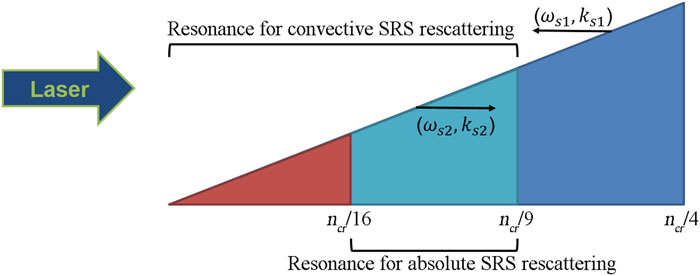
    A schematic representation of BSRS and Re-SRS is presented in Fig. 1. BSRS light generated primarily at ncr/4 encounters its quarter critical density at ncr/16, where it can excite absolute SRS rescattering modes if it is intense enough. BSRS light generated primarily at a slightly lower density than ncr/4 encounters its corresponding quarter critical density point slightly above ncr/16, and so on. The respective resonance points for primary and secondary SRS become closer as the primary SRS occurs at lower densities, until they converge to a density at which the BSRS light encounters its corresponding quarter critical density locally. This density is readily found to be nncr/9 using the matching conditions and dispersion relations for primary and secondary SRS: ω0ωp + ωs1 and ωpωs1/2 yield ωpω0/3, i.e., nncr/9.

    Schematic of the resonant regions for absolute and convective modes of Re-BSRS instabilities in an inhomogeneous plasma.

    Figure 1.Schematic of the resonant regions for absolute and convective modes of Re-BSRS instabilities in an inhomogeneous plasma.

    Therefore, in the special density range [ncr/16, ncr/9], absolute modes of Re-SRS can be stimulated, given sufficient intensity of the BSRS light coming from the higher-density side.

    Below ncr/16, absolute Re-SRS modes cannot be stimulated, since primary BSRS light is unable to find its corresponding quarter-critical-density point in this region. Convective Re-SRS modes are still allowed to be stimulated, and convective amplification along their propagation path can still be energetically important.

    III. SIMULATION CONFIGURATIONS

    We have performed a series of 1D and 2D PIC simulations of SP-LPI with the parameters appropriate to SG-II planar-target experimental conditions, using the electromagnetic PIC code OSIRIS.25 The detailed parameters are listed in Table I. The findings from the SG-II experiments will be published in another paper.

    CaseDim.λ (μm)I0 (W/cm2)Te (keV)Ti (keV)L (μm)α50 (%)
    (i)1D1.0541.2 × 101610.511803.1
    (ii)1D1.0545 × 101510.511802.0
    (iii)1D1.0543 × 101510.511800.2
    (iv)1D1.0541 × 101510.511800.08
    (v)1D1.0548 × 101510.511802.8
    (vi)2D1.0541.2 × 101610.511805.0

    Table 1. Simulation parameters.

    For the 1D simulations, the electron density ranges from 0.01ncr to 0.22ncr. An exponential density profile is used: n(x) = n0 exp(x/L), where n0 = 0.01ncr and the density scale length L = 1180 µm. Two species of ions, C and H, are used, with a number density ratio 1:1. The electron and ion temperatures are Te = 1 keV and TC = TH = 0.5 keV, respectively. A typical 1D simulation [case (i)] region is 3.35 mm long with grid size Δx = 0.2c/ω0. Open (i.e., nonreflection) boundary conditions are applied for fields and absorbing boundary conditions for particles in the 1D simulations. The 2D simulation [case (vi)] box is 2012 × 60 µm2, with grid 60 000 × 1800 and Δx = Δy = 0.2c/ω0, covering an electron density range from 0.04ncr to 0.26ncr. Open boundary conditions are applied for fields and thermal reflection boundary conditions for particles along the longitudinal (x) direction. The transverse (y) direction is set to be periodic, which is appropriate for a large laser spot regime as in the SG-II experiments. The same L and temperatures are used in the 2D as in the 1D simulations. In both 1D and 2D simulations, 100 particles per species per cell are used, with electron–ion collisions taken into account.

    GBSRS=vosc2k0L=I14λμLμ22001nncr>1,where vos is the electron oscillatory velocity in the driver laser’s electric field, and I14, λμ, and Lμ are the intensity of the driver laser (=I0), the wavelength in vacuum of the driver laser, and the electron density scale length (=L) in units of 1014 W/cm2, μm, and μm, respectively. For our lowest laser peak intensity in this work, namely, I0 = 1 × 10¹⁵ W/cm2, and a typical density n = 0.1ncr, we have GBSRS = 5. Therefore, the peak value I0 is above the convective BSRS threshold in this regime, with significant BSRS processes to be expected.

    IV. SIMULATION RESULTS AND DISCUSSION

    Laser propagation in a large-scale-length plasma takes time. Therefore, although short laser pulses last for only ∼4 ps, the simulations are performed for ∼35 ps to allow all of the light signals to be eventually collected by the diagnostic at the left boundary so that the integrated fraction of the scattered light can be obtained; see Fig. 2. This configuration is adopted to allow a fair comparison with future experiments where time-integrated SRS signals will be measured.

    Evolution of the Ey field (contributed only by the laser’s electric field in 1D simulations) of simulation case (i) in x–t space.

    Figure 2.Evolution of the Ey field (contributed only by the laser’s electric field in 1D simulations) of simulation case (i) in xt space.

    The 1D simulations restrict the SRS modes to be either backward or forward. Thus, clean BSRS and FSRS signals can be obtained in 1D simulations. Also, in our 1D simulations, very high spatial and temporary resolutions can be achieved for sophisticated spectral analysis. The 2D simulations are performed not only for validation of the physical picture found in the 1D simulations, but also to evaluate 2D effects such as TPD modes generated by rescattered light.

    The scope of the LPI evolution in the simulation of case (i) is shown in Fig. 2. In case (i), the incident laser intensity is sufficiently high that many types of LPI are stimulated. The incident laser pulse shines from the left boundary and propagates to the right. The various types of scattered light and their generation regions can be identified clearly from a combination of the light propagation information in Fig. 2 and the frequency spectra in Figs. 3 and 4. On the incident laser’s path, BSRS and BSBS are first excited in the low-density plasma that first encounters the incident light. These two types of light propagate directly to the left and are caught early by the collector located at the left boundary. The BSRS light is intense enough to stimulate secondary FSRS (Re-FSRS) in the low-density region below ncr/16.

    Time-resolved Ey2 spectrum of light collected at the left boundary for (a) case (i); (b) case (ii), and (c) case (iii). Different types of LPI signals can be identified, as indicated. The dashed lines are the boundaries of the primary BSRS modes.

    Figure 3.Time-resolved Ey2 spectrum of light collected at the left boundary for (a) case (i); (b) case (ii), and (c) case (iii). Different types of LPI signals can be identified, as indicated. The dashed lines are the boundaries of the primary BSRS modes.

    Snapshots of the in-flight Ey2 spectrum in the simulation of case (i) at (a) t = 6.0 ps, (b) t = 8.5 ps, and (c) t = 14.0 ps. Different types of LPI signals are indicated. The dashed lines in (c) are the turning points of the rescattered light with a range of frequencies.

    Figure 4.Snapshots of the in-flight Ey2 spectrum in the simulation of case (i) at (a) t = 6.0 ps, (b) t = 8.5 ps, and (c) t = 14.0 ps. Different types of LPI signals are indicated. The dashed lines in (c) are the turning points of the rescattered light with a range of frequencies.

    The dominance of Re-FSRS over Re-BSRS in the low-density region is due to Landau damping of the EPWs. The Re-BSRS EPWs in that density region are heavily Landau-damped because their phase velocities vp = ωEPW2/kEPW2 are close to the local ambient electron thermal velocity. However, as the incident light propagates toward higher-density regions, kEPW2 decreases gradually and ωEPW2 increases, which leads to a decrease in Landau damping. The dominant rescattering mode then switches from Re-FSRS to Re-BSRS as ne increases.

    Then, Re-BSRS starts to appear in the density region near ncr/16 and above. The Re-BSRS light is generated propagating to the right. It is then reflected at its corresponding critical-density point, propagating to the left, low-density, direction and contributing to the spectrum collected at the left boundary at later times. Only part of the early rising phase of the incident laser pulse can be transmitted through this large-scale plasma and reach the right boundary, while most of the incident light is depleted, as shown in Fig. 2.

    t(ωs)=0x1vg0dx+0x1vgsdx+tgrow,where vg0 and vgs are the local group velocities of the incident and scattered light, respectively. The three terms on the right-hand side respectively represent the time taken for the incident laser light to arrive from the left boundary, the time taken for the BSRS light to reach the left boundary, and the characteristic growth time for the BSRS mode. The dependence of tgrow on ωs can be neglected in the low-density region (nncr/4) compared with the first two terms. After ∼15 ps, Re-BSRS signals with 0.33ω0 < ω < 0.5ω0 start to appear in the spectrum. Re-BSRS light is generated moving forward, is reflected at different critical-density points depending on its frequency, and reaches the left boundary at different times, as shown in Fig. 3(a).

    Re-SRS can be stimulated once the primary BSRS is intense enough, with its level depending on I0. The same kind of spectra for cases (ii) and (iii) are shown in Figs. 3(b) and 3(c), where I0 is 5 × 10¹⁵ W/cm2 and 3 × 10¹⁵ W/cm2, respectively. In case (ii), all the LPI signals are weaker. Re-FSRS is barely visible, while Re-BSRS is observable but weaker. In case (iii), only the BSRS signals can be clearly observed in the spectrum, with a dim signal at about ωs2 = 0.33ω0 due to the absolute modes of Re-BSRS, which indicates that I0 = 3 × 10¹⁵ W/cm2 is close to the threshold for Re-BSRS under this specified set of plasma parameters. Despite the lowest threshold of the absolute Re-SRS mode at ωs2 = 0.33ω0, this mode is not energetically dominant in the high-I0 cases, as shown in Figs. 3(a) and 3(b).

    By application of a windowed Fourier transform in both space and time, the detailed in-flight spectra showing the evolution of all LPI signals at different stages in case (i) are obtained and are shown in Fig. 4. Forward- and backward-propagating light can be distinguished via negative and positive ω in the spectra. The incident laser pulse is located around ω = −ω0. Figure 4(a) shows the early stage of the simulation: the incident laser pulse is propagating in the low-density region of the plasma (n < 0.1ncr); on its way, backward-propagating light is generated via primary BSRS and BSBS and by Re-FSRS in different frequency ranges. The BSBS modes are at ωs1ω0, since the ion-acoustic frequency is orders of magnitude lower than ω0. The BSRS modes generated in the low-density region (n < 0.1ncr) have a high frequency (ωs1ω0ωp > 0.7ω0). The BSRS light is intense enough to generate a secondary FSRS locally, whose frequencies then lie in the range 0.4ω0 < ωs2 < 0.7ω0, consistent with the spectrum shown in Fig. 4(a).

    As the incident laser pulse reaches the higher-density region, the frequency of the BSRS light shifts to the red. The BSRS light starts to generate Re-BSRS, whose daughter light waves propagate forward; see Fig. 4(b). The forward-propagating Re-BSRS light follows the incident pulse and propagates continuously in a bath of the primary broadband BSRS light. The broadband BSRS spectrum contains resonant components that are able to satisfy the three-wave matching conditions with the Re-BSRS light, such that the Re-BSRS light can be convectively amplified during its propagation until the local electron density is too high and the primary BSRS is red-shifted too far to be resonant. The amplification of Re-BSRS is energetically important and depletes the BSRS light, as demonstrated by the darker region (x from 7000c/ω0 to 10 000c/ω0) in the BSRS spectrum in Fig. 4(b). While BSRS light stimulates significant Re-SRS in the low-density regions, we do not observe secondary scattering simulated by BSBS. The growth of BSBS is likely limited by the short pulse duration of the incident laser, and its secondary processes are not expected to be significant.

    The Re-BSRS light continues to propagate forward until it encounters its corresponding critical density. It is then reflected and eventually collected by the diagnostic at the left boundary after t = 20 ps; see the reflected light in Fig. 2 and the spectra in Figs. 3(a) and 4(c). The critical-density surfaces for the Re-BSRS lights are shown by the dashed lines in Fig. 4(c). The time at which Re-BSRS light reaches the left boundary depends on the distance along its optical path, which is determined by its group velocity and the position of its critical density. That is the reason for the higher-frequency signal being caught at a later time in Figs. 3(a) and 3(b).

    The energy carried by rescattered light is sensitive to the peak intensity of the incident laser pulse. Figure 5(a) shows the time-integrated energy fraction carried by the backward-scattered light (i.e., collected by the left boundary) at two different frequency ranges in a series of simulations with a number of incident laser intensities as listed in Table I. The energy fraction of the high-frequency ([0.5, 0.95]ω0) components, usually considered experimentally as the frequency range of the BSRS light, is plotted as circles in the figure, while the energy fraction of the low-frequency ([0.32, 0.5]ω0) components is plotted as stars. The high-frequency fraction rises sharply at I0 ∼ (1–3) × 1015 W/cm2, then saturates and even slightly drops for higher intensities. When I0 < 3 × 10¹⁵ W/cm2, SRS is likely to be in the linear regime, and so the SRS reflectivity is sensitive to I0. The I0 dependence of the high-frequency light fraction is qualitatively consistent with the experimental observations for SRS reflectivity vs laser intensity shown in Fig. 5 of Ref. 27. The low-frequency fraction (mostly attributed to Re-BSRS but partly to Re-FSRS) continues to increase with I0 and becomes more energetically important for higher I0 (5.9% at I0 = 1.2 × 10¹⁶ W/cm2). Both Re-BSRS and Re-FSRS deplete the primary BSRS light, consequently reducing the energy fraction of the high-frequency light signals. They may also help explain the slight drop in SRS reflectivity vs I0 shown in Fig. 5 of Ref. 27 at high laser intensities. The depletion of the primary BSRS light due to Re-BSRS could lead to an underestimate of the primary BSRS process.

    Time-integrated reflection fraction (a) due to backward-traveling light in different frequency ranges and (b) due to different types of LPI.

    Figure 5.Time-integrated reflection fraction (a) due to backward-traveling light in different frequency ranges and (b) due to different types of LPI.

    The reason for classifying the scattered light by frequency is to provide a bridge between the simulation results and the time-integrated experimental diagnostics. However, in this way, the Re-FSRS modes are also mostly counted in the high-frequency spectra, which will affect the accuracy of measuring the pure primary BSRS levels. Since all types of LPI modes are distinguishable in our spectra (see Fig. 3), we are able to plot the energy fraction for each type in Fig. 5(b) by integrating the spectra of Fig. 3. This is also an advantage of SP-LPI studies, since it is usually very challenging to distinguish the LPI signals in the spectrum of a long-pulse simulation. The fraction of BSRS continues to decrease when I0 is above 3 × 10¹⁵ W/cm2, since the BSRS light transfers more and more energy to Re-BSRS and Re-FSRS. The fractions of both Re-BSRS and Re-FSRS increase with I0. Re-BSRS appears to have a lower threshold, whereas Re-FSRS becomes dominant over Re-BSRS for larger pump intensities.

    Both stronger drivers and longer amplification distance would facilitate convective amplification. However, there is not yet any indication of saturation for Re-BSRS modes up to I0 = 1.2 × 10¹⁶ W/cm2, while the BSRS light that serves as the driver of Re-BSRS has already reached a saturated level when I0 > 3 × 10¹⁵ W/cm2, as shown in Fig. 5(b). The spatial-frequency distributions of the primary BSRS modes are shown at different times in Figs. 6(a) and 6(c) for case (i) and in Figs. 6(b) and 6(d) for case (ii). It can be seen that the amplitude of the primary BSRS light does not increase much when I0 increases from 5 × 10¹⁵ W/cm2 to 1.2 × 10¹⁶ W/cm2, while Fig. 5(b) tells us that the total fraction of Re-BSRS increases from 2.5% to 5.0%.

    [(a)–(d)] Comparison of the backward-propagating light spectra within the frequency range of [0.6, 0.95]ω0 in cases (i) [(a) and (c)] and (ii) [(b) and (d)]. (e) Comparison of the convective amplification of a forward-propagating Re-BSRS light component with ωs2 = 0.47ω0 in cases (i) and (ii). The star symbols in (a)–(d) represent the most resonant light component that can serve as a pump for the Re-BSRS mode ωs2 = 0.47ω0 at the given moment. The circles and triangles in (e) represent the peak values vs the peak’s positions on the Ey2 envelope at different times in cases (i) and (ii). Snapshots of the Ey2 envelopes at three different times in case (i) are plotted as dashed curves.

    Figure 6.[(a)–(d)] Comparison of the backward-propagating light spectra within the frequency range of [0.6, 0.95]ω0 in cases (i) [(a) and (c)] and (ii) [(b) and (d)]. (e) Comparison of the convective amplification of a forward-propagating Re-BSRS light component with ωs2 = 0.47ω0 in cases (i) and (ii). The star symbols in (a)–(d) represent the most resonant light component that can serve as a pump for the Re-BSRS mode ωs2 = 0.47ω0 at the given moment. The circles and triangles in (e) represent the peak values vs the peak’s positions on the Ey2 envelope at different times in cases (i) and (ii). Snapshots of the Ey2 envelopes at three different times in case (i) are plotted as dashed curves.

    As an example, the convective amplification of an Re-BSRS mode at ωs2 = 0.47ω0 is shown for cases (i) and (ii) in Fig. 6(e). In both cases, the mode has distinguished amplification distances and gains. The spectral broadening of the BSRS EPW for higher I0 also contributes to the amplification boosting of the Re-BSRS modes. As Re-BSRS light travels in a bath of primary BSRS light, the BSRS light satisfying ωs1 = ωs2 + ωEPW2 (indicated by stars in Fig. 6) can contribute to the convective amplification. In Figs. 6(a) and 6(b), the matching-condition stars are both located inside the BSRS light spectrum, which indicates that the ωs2 = 0.47ω0 mode can be amplified at this moment in both cases. The amplification stops when the Re-BSRS light reaches a high-density point at which it is not able to pick up any pump component from the BSRS spectrum. As can be seen from Figs. 6(c) and 6(d), although the matching-condition star is still located inside the BSRS light spectrum in case (i), it is outside the spectrum in case (ii). Therefore, the ωs2 = 0.47ω0 mode is still being amplified in case (i), but has already saturated in case (ii) when t > 10 ps, as shown in Fig. 6(e).

    vpcωs2ωp2+2ωs2ωp±ωs2ωp21,where the plus and minus signs correspond to Re-BSRS and Re-FSRS, respectively. Equation (6) is valid unless the electron density is too low to allow the thermal terms in the EPW dispersion relations to be ignored. The EPWs associated with Re-FSRS have high phase velocities. As an estimate, using Eq. (6), the lower limit of the frequency of Re-FSRS light at ωs2 ≈ 0.5ω0 and its resonant density at n = 0.06ncr yield vp,Re-FSRS = 0.9c, which is much faster than the electron thermal velocity in a 1 keV plasma. The minimum phase velocity of the Re-BSRS EPWs is vp,Re-BSRS ≈ 0.2c, which is much lower than vp,Re-FSRS. Therefore, Re-FSRS EPWs are expected to couple inefficiently with thermal electrons in the ambient plasma, while Re-BSRS EPWs, with their lower phase velocities, couple more easily with thermal electrons and accelerate them to high energies. It can be seen that on setting ωs2ωp, Eq. (6) yields a hot-electron kinetic energy of ∼170 keV generated by the EPWs near ncr/9, which is similar to the value found in Ref. 23. However, the hot electrons associated with the Re-BSRS EPWs have a broad energy range in our cases owing to the Re-BSRS convective amplification over a large density range.

    The temporal–spatial distributions of the Re-BSRS modes and the backward-moving hot electrons >50 keV are shown in Figs. 7(a) and 7(b), respectively. There is a strong correlation between the two. We denote by α50 the time-integrated kinetic energy carried by the backward-moving hot electrons >50 keV normalized to the total incident laser energy. The dependence of α50 on I0 is shown in Table I.

    Correlation of hot electrons with Re-BSRS. (a) Temporal and spatial evolution of Re-BSRS light within the frequency range 0.35ω0 ωs2 ω0. (b) Temporal and spatial evolution of the distribution of the backward-moving hot electrons with kinetic energies >50 keV. The presence of a bunch of hot electrons near the left boundary after t ≈ 18 ps is probably due to the boundary conditions in the long-time simulation and is expected to be artificial.

    Figure 7.Correlation of hot electrons with Re-BSRS. (a) Temporal and spatial evolution of Re-BSRS light within the frequency range 0.35ω0 < ωs2 < 0.5ω0. (b) Temporal and spatial evolution of the distribution of the backward-moving hot electrons with kinetic energies >50 keV. The presence of a bunch of hot electrons near the left boundary after t ≈ 18 ps is probably due to the boundary conditions in the long-time simulation and is expected to be artificial.

    We also perform a 2D PIC simulation under the same plasma conditions to verify the convective amplification process of Re-SRS in two dimensions [case (vi) of Table I]. It is numerically challenging to apply the analysis in 2D simulations with the same temporal and spatial resolutions as in our 1D analysis, and so a spectrum in kx space is used to identify different types of LPI modes, as shown in Fig. 8(a), which depicts the temporal evolution of the spatial Fourier transform of the transversely averaged Ey field applied in a spatial domain near ncr/9. The incident and BSBS light both contribute to the signals at k ≈ 0.91ω0/c. Wave numbers ks1 in the range from 0.4ω0/c to 0.6ω0/c represent the BSRS light, while the Re-BSRS light starts to show up at ks2 ≈ 0.2ω0/c after 4 ps, by which time the BSRS signals are well established.

    2D simulation results for case (vi). (a) Time evolution of Ey2 in kx space in a spatial domain near ne = ncr/9. (b) Evolution of Ey2 of the mode ωs2 = 0.4ω0. The circles represent the peak value vs the peak’s position on the envelope at different times, while three snapshots of the envelopes at three different times are shown by dashed lines.

    Figure 8.2D simulation results for case (vi). (a) Time evolution of Ey2 in kx space in a spatial domain near ne = ncr/9. (b) Evolution of Ey2 of the mode ωs2 = 0.4ω0. The circles represent the peak value vs the peak’s position on the envelope at different times, while three snapshots of the envelopes at three different times are shown by dashed lines.

    Significant convective amplification of the Re-BSRS light has also been observed in the 2D simulation. The Re-BSRS light at different frequencies propagates forward, passes the signal collecting domain near ncr/9 from 4 ps to 8 ps, and then revisits this domain at t > 8 ps after it has been reflected at its corresponding critical density, as indicated in the spectrum in Fig. 8(a). Figure 8(b) shows the convective amplification of Re-BSRS light with ωs2 = 0.4ω0 along its propagation path, consistent with the 1D simulation results.

    The spectra of light and plasma waves in Figs. 9(a) and 9(b) show rich 2D features in addition to the BSRS and Re-BSRS processes. The LPI processes are identified and indicated on Fig. 9. Without the limitations of 1D geometry, both BSRS and Re-BSRS have larger spread angles. Secondary TPD driven by the primary BSRS near ncr/9 can be observed in the plasma wave spectrum in Fig. 9(b). TPD involves pairs of EPWs and generates no light waves. The EPWs with smaller kx generated by the secondary TPD can be seen near kx ≈ 0.2ω0/c, and the EPWs with larger kx are mixed with the EPWs associated with Re-BSRS near kx ≈ 0.6ω0/c. The hot-electron fraction is a few times larger than in the 1D simulation for case (i), which could be attributed to the secondary TPD. The transversely periodic configuration in our 2D simulation is relevant to a large-focal-spot scenario where the laser spot size is much larger than the transverse size of the simulation box. Important higher-dimensional physics such as spot-size effects should be studied with appropriate boundary conditions in future work.

    Spectra in ky–kx space of (a) Bz representing incident and scattered light and (b) electron number density representing plasma waves in the region with a background density range of [0.06ncr, 0.11ncr] at t = 4.1 ps in case (vi).

    Figure 9.Spectra in kykx space of (a) Bz representing incident and scattered light and (b) electron number density representing plasma waves in the region with a background density range of [0.06ncr, 0.11ncr] at t = 4.1 ps in case (vi).

    V. SUMMARY AND CONCLUSIONS

    To summarize, we have studied a novel scenario in the SP-LPI regime with parameters relevant to SG-II experiments. The plasma has a large density scale length together with a broad density range in this regime, which facilitates the generation and convective amplification of Re-BSRS modes. It is found that when the incident laser intensity is well above its BSRS threshold, the backscattered daughter light wave of BSRS can also excite secondary BSRS and FSRS in the region below ncr/9 of the incident laser. The daughter light wave can be amplified via Re-BSRS as it propagates toward the higher-density region in the bath of broadband light generated by the primary BSRS process.

    Sensitively correlated with the incident laser intensity I0, convective amplification makes the Re-BSRS modes energetically important for high I0. Re-BSRS can deplete the primary BSRS light significantly, which can be considered an energy sink that could lead to an underestimate of the primary BSRS levels in experiments. Higher I0 not only drives more intense BSRS light, but also broadens its spectrum and thus enhances its amplification distance. Both effects increase the convective gain of Re-BSRS. A significant number of backward-moving hot electrons are generated. This hot-electron generation is found to be strongly correlated with the EPWs associated with Re-BSRS.

    The findings of this work indicate that Re-SRS could be considered a concern for higher-intensity ignition-scale regimes. First, the depletion of the primary BSRS due to Re-SRS may lead to an underestimate of the primary BSRS level in an SP-LPI experiment and possibly in a long-pulse ignition-scale experiment. Second, the backward-moving hot electrons also represent a significant energy loss, but one likely to be missed by the conventional hard-x-ray diagnostics that are usually deployed on the higher-density side of the plasmas. Last, but not least, the EPWs generated via Re-SRS will eventually pass their energy to the ambient plasma via collisional damping and change the local plasma temperature on a longer time scale.

    References

    [1] J. D. Lindl. Inertial Confinement Fusion(1998).

    [2] C. Cavailler. Inertial fusion with the LMJ. Plasma Phys. Controlled Fusion, 47, B389-B403(2005).

    [3] Z. Dang, B. Feng, Y. Chen, X. Yuan, X. Deng, W. Dai, W. Zhou, H. Jia, Z. Peng, W. Zheng, F. Wang, D. Hu, X. Wei, F. Jing, D. Xu, L. Liu, F. Wang, L. Guo, Y. Xiang, X. Zhang, Q. Zhu, R. Zhang, X. Xie, D. Lin. Laser performance upgrade for precise ICF experiment in SG-III laser facility. Matter Radiat. Extremes, 2, 243-255(2017).

    [4] Z. Liu, G. Zhang, D. Li, J. Zhu, H. Tao, X. Jiao, Y. Zhang, M. Sun, P. Yang, X. Xie, P. Zhu, C. Liu, B. Wang, G. Xu, Z. Jiao, W. Ma, L. Ren, H. Huang, X. Lu, L. Wang, X. Ouyang, D. Liu, J. Wang, B. Zhu, Z. Lin, Q. Fan, D. Liu, L. Yang, S. Zhou, M. Sun, X. Li, W. Fan, J. Zhu. Status and development of high-power laser facilities at the NLHPLP. High Power Laser Sci. Eng., 6, e55(2018).

    [5] M. A. Barrios, A. A. Solodov, J. D. Moody, W. Seka, E. M. Campbell, J. F. Myatt, R. W. Short, J. E. Ralph, P. Michel, T. Chapman, C. Goyon, J. W. Bates, M. Hohenberger, M. J. Rosenberg, R. Epstein, S. P. Regan. Origins and scaling of hot-electron preheat in ignition-scale direct-drive inertial confinement fusion experiments. Phys. Rev. Lett., 120, 055001(2018).

    [6] H. Wen, R. Yan, A. V. Maximov, C. Ren. Linear regime of two-plasmon decay and stimulated Raman scattering instability near the quarter-critical density in plasmas. Phys. Plasmas, 22, 052704(2015).

    [7] M. Tabak, J. Hammer, S. C. Wilks, M. D. Perry, M. E. Glinsky, W. L. Kruer, J. Woodworth, R. J. Mason, E. M. Campbell. Ignition and high gain with ultrapowerful lasers. Phys. Plasmas, 1, 1626-1634(1994).

    [8] P. Mounaix, G. D. Enright, S. Baton, H. A. Baldis, B. La Fontaine, W. Rozmus, D. M. Villeneuve, C. Labaune, D. Pesme, M. Casanova. Stimulated Brillouin scattering in picosecond time scales: Experiments and modeling. Phys. Fluids B, 5, 3319-3327(1993).

    [9] M. Louis-Jacquet, S. Gary, C. Labaune, N. Renard, S. D. Baton, C. Rousseaux, H. A. Baldis, P. Mounaix, B. La Fontaine, D. Pesme. Stimulated Brillouin scattering with a 1 ps laser pulse in a preformed underdense plasma. Phys. Rev. E, 49, R3602-R3605(1994).

    [10] C. Rousseaux, S. D. Baton, P. Mounaix, J. L. Miquel, G. Malka, F. Amiranoff. Experimental validation of the linear theory of stimulated Raman scattering driven by a 500-fs laser pulse in a preformed underdense plasma. Phys. Rev. Lett., 74, 4655-4658(1995).

    [11] S. D. Baton, M. Rabec le Gloahec, C. Rousseaux, P. Mora, J. Fuchs, L. Gremillet, F. Amiranoff, J. C. Adam, A. Héron. Strong absorption, intense forward-Raman scattering and relativistic electrons driven by a short, high intensity laser pulse through moderately underdense plasmas. Phys. Plasmas, 9, 4261-4269(2002).

    [12] A. Héron, C. Rousseaux, S. D. Baton, J. C. Adam, F. Amiranoff, M. Rabec Le Gloahec, P. Loiseau, M. Casanova, L. Gremillet. Transient development of backward stimulated Raman and Brillouin scattering on a picosecond time scale measured by subpicosecond Thomson diagnostic. Phys. Rev. Lett., 97, 015001(2006).

    [13] D. J. Strozzi, J. C. Adam, S. D. Baton, F. Amiranoff, L. Gremillet, A. Héron, D. Bénisti, C. Rousseaux. Experimental evidence of predominantly transverse electron plasma waves driven by stimulated Raman scattering of picosecond laser pulses. Phys. Rev. Lett., 102, 185003(2009).

    [14] B. J. Albright, W. Daughton, K. J. Bowers, L. Yin, H. A. Rose. Saturation of backward stimulated scattering of a laser beam in the kinetic regime. Phys. Rev. Lett., 99, 265004(2007).

    [15] D. Bénisti, F. Philippe, B. B. Afeyan, S. D. Baton, J. L. Kline, D. S. Montgomery, B. Loupias, F. Amiranoff, V. Tassin, C. Rousseaux, L. Gremillet. Experimental investigation of stimulated Raman and Brillouin scattering instabilities driven by two successive collinear picosecond laser pulses. Phys. Rev. E, 93, 043209(2016).

    [16] C. D. Zhou, W. Theobald, R. Betti, A. A. Solodov, L. J. Perkins, K. S. Anderson. Shock ignition of thermonuclear fuel with high areal density. Phys. Rev. Lett., 98, 155001(2007).

    [17] L. J. Perkins, K. N. LaFortune, R. Betti, W. H. Williams. Shock ignition: A new approach to high gain inertial confinement fusion on the National Ignition Facility. Phys. Rev. Lett., 103, 045004(2009).

    [18] Z. F. Fan, J. F. Wu, L. F. Wang, W. H. Ye, X. T. He, K. Lan, J. Liu, J. W. Li. A hybrid-drive nonisobaric-ignition scheme for inertial confinement fusion. Phys. Plasmas, 23, 082706(2016).

    [19] D. E. Hinkel, A. B. Langdon. Nonlinear evolution of stimulated scatter in high-temperature plasmas. Phys. Rev. Lett., 89, 015003(2002).

    [20] B. J. Winjum, F. S. Tsung, J. E. Fahlen, W. B. Mori. Anomalously hot electrons due to rescatter of stimulated Raman scattering in the kinetic regime. Phys. Rev. Lett., 110, 165001(2013).

    [21] S. Weber, O. Klimo, V. T. Tikhonchuk, J. Limpouch. Particle-in-cell simulations of laser-plasma interaction for the shock ignition scenario. Plasma Phys. Controlled Fusion, 52, 055013(2010).

    [22] W. D. Liu, R. Yan, J. Li, C. Ren, L. Hao. Nonlinear fluid simulation study of stimulated Raman and Brillouin scatterings in shock ignition. Phys. Plasmas, 24, 062709(2017).

    [23] S. Weng, J. Zhu, S. Ji, Z. Sheng, Y. Zhao. Absolute instability modes due to rescattering of stimulated Raman scattering in a large nonuniform plasma. High Power Laser Sci. Eng., 7, e20(2019).

    [24] W. L. Kruer. The Physics of Laser Plasma Interactions(2003).

    [25] L. O. Silva, F. S. Tsung, S. Lee, S. Deng, R. A. Fonseca, J. C. Adam, W. B. Mori, T. Katsouleas, W. Lu, C. Ren, V. K. Decyk. Osiris: A three-dimensional, fully relativistic particle in cell code for modeling plasma based accelerators. Lect. Notes Comput. Sci., 2331, 342(2002).

    [26] M. N. Rosenbluth, C. S. Liu, R. B. White. Raman and Brillouin scattering of electromagnetic waves in inhomogeneous plasmas. Phys. Fluids, 17, 1211(1974).

    [27] R. J. Focia, D. S. Montgomery, R. P. Johnson, H. A. Rose, D. A. Russell, J. C. Fernández, N. Renard-Legalloudec, J. A. Cobble. Recent trident single hot spot experiments: Evidence for kinetic effects, and observation of Langmuir decay instability cascade. Phys. Plasmas, 9, 2311-2320(2002).

    Yu Ji, Chang-Wang Lian, Rui Yan, Chuang Ren, Dong Yang, Zhen-Hua Wan, Bin Zhao, Chen Wang, Zhi-Heng Fang, Jian Zheng. Convective amplification of stimulated Raman rescattering in a picosecond laser plasma interaction regime[J]. Matter and Radiation at Extremes, 2021, 6(1): 015901
    Download Citation