Xiaodong Cai1、†, Rong Tang1, Haoyang Zhou2, Qiushi Li1, Shaojie Ma2, Dongyi Wang2, Tong Liu2, Xiaohui Ling2、3, Wei Tan4、5, Qiong He2、6、7, Shiyi Xiao1、*, and Lei Zhou2、7、*
Author Affiliations
1Shanghai University, Key Laboratory of Specialty Fiber Optics and Optical Access Networks, Joint International Research Laboratory of Specialty Fiber Optics and Advanced Communication, Shanghai Institute for Advanced Communication and Data Science, Shanghai, China2Fudan University, State Key Laboratory of Surface Physics, Key Laboratory of Micro and Nano Photonic Structures (Ministry of Education) and Physics Department, Shanghai, China3Hengyang Normal University, College of Physics and Electronic Engineering, Hengyang, China4CAEP, Microsystem and Terahertz Research Center, Chengdu, China5CAEP, Institute of Electronic Engineering, Mianyang, China6Fudan University, Academy for Engineering and Technology, Shanghai, China7Collaborative Innovation Centre of Advanced Microstructures, Nanjing, Chinashow less
DOI: 10.1117/1.AP.3.3.036003
Cite this Article
Set citation alerts
Xiaodong Cai, Rong Tang, Haoyang Zhou, Qiushi Li, Shaojie Ma, Dongyi Wang, Tong Liu, Xiaohui Ling, Wei Tan, Qiong He, Shiyi Xiao, Lei Zhou. Dynamically controlling terahertz wavefronts with cascaded metasurfaces[J]. Advanced Photonics, 2021, 3(3): 036003
Copy Citation Text
show less
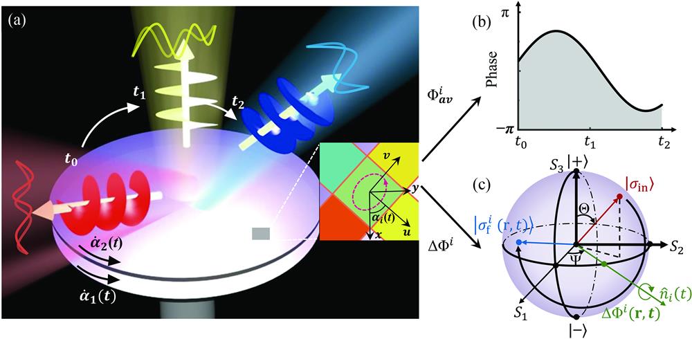
Fig. 1. Schematic of the cascaded metasurface for dynamic wavefront control. (a) Sketch of the dynamic wavefront controlling process in which the direction and polarization state of the transmitted wave are evolving simultaneously over the time . The whole system is composed of multilayer metasurfaces with different phase distributions and angular speeds (where the indicates the layer number). The inset to panel (a) illustrates the local coordinate of a meta-atom and the global coordinate. Such a meta-atom can transmit a normally incident wave with (b) an averaged transmission phase and (c) different polarization states (described by the point on Poincaré’s sphere) evolving simultaneously over the time .
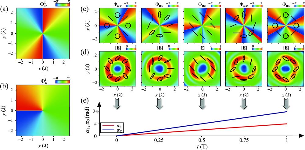
Fig. 2. Illustration of the dynamic controlling process. Two identical transparent metasurfaces with (a) phase distribution of and (b) phase distribution of are employed to illustrate the process. (c) The total phase of the device and (d) the scattered -field distributions calculated by the Green’s function approach for a transmitted beam at a distance above the surface for a normally incident LCP wave at five different time instants, with (e) the orientation angles evolving over time . Ellipses in (c) and (d) illustrate the polarization patterns at different locations inside the transmitted beam at a distance and above the surface.
Fig. 3. Meta-atom designs for both the phase and polarization manipulations. (a) Schematic of the designed meta-atom for independent phase and polarization controlling. FDTD-computed (b) transmission phase difference and (c) average transmission amplitude versus and for the bottom post under illuminations of - and -polarized beams, with fixed . (d) Simulated average transmission phase and (e) average transmission amplitude versus and for the whole meta-atom with after optimization of the bottom post. Other geometrical parameters of the meta-atoms are fixed as and .
Fig. 4. Beam-steering process of transmitted waves along different paths. The phase diagrams of (a) polar angle and (b) azimuth angle as functions of and . The and change as functions of when the beam direction varies on (c) Path I and (d) Path II.
Fig. 5. Experimental and simulated results of the dynamic beam-steering metadevice. (a) Schematics of the metadevice consisting of two layers of transmissive metasurfaces aligned by a motorized rotation stage, as shown in the lower left inset. The upper left inset shows the side-view SEM pictures of a single metasurface, which consists of top and bottom layers. (b) Top-view (left) and (c) bottom-view (right) SEM pictures of the fabricated metadevice. (d) Schematics of the experimental setup to characterize the metadevice. (e) Experimental and (f) simulated far-field scattering power distributions as the metadevice is illuminated by an LCP light at 0.7 THz, as the metadevice evolves along Path I at different time instants. (g) Evolution of directions for transmitted waves on the sphere of direction as the metadevice moves along Path I and Path II, with solid line (star-symbols) denoting the simulated (experimental) results. Here, the blue region denotes the solid angle for beam-steering coverage.
Fig. 6. Experimental and simulated results of the metadevice for simultaneous beam-steering and polarization manipulation. (a) Rotation operations on Poincaré’s sphere for an LCP incident wave passing through the two-layer cascaded metasurfaces. (b) The phase distribution of and of two identical anisotropic metasurfaces. (c) SEM images of the top and bottom of the designed meta-atoms. The evolution of (d) directions on a sphere of direction and (e) the polarization states on Poincaré’s sphere for transmitted waves varying over time, where the blue region denotes the beam-steering and polarization coverage and the star-symbols represent the and polarization state at three different time instants []. (f)–(h) Experimental (blue circles) and simulated (blue line) far-field scattering patterns (left panel) and polarization states (right panel) of the transmitted wave of three certain time instants.