1Shanghai University, Key Laboratory of Specialty Fiber Optics and Optical Access Networks, Joint International Research Laboratory of Specialty Fiber Optics and Advanced Communication, Shanghai Institute for Advanced Communication and Data Science, Shanghai, China
2Fudan University, State Key Laboratory of Surface Physics, Key Laboratory of Micro and Nano Photonic Structures (Ministry of Education) and Physics Department, Shanghai, China
3Hengyang Normal University, College of Physics and Electronic Engineering, Hengyang, China
4CAEP, Microsystem and Terahertz Research Center, Chengdu, China
5CAEP, Institute of Electronic Engineering, Mianyang, China
6Fudan University, Academy for Engineering and Technology, Shanghai, China
7Collaborative Innovation Centre of Advanced Microstructures, Nanjing, China
Dynamically controlling terahertz (THz) wavefronts in a designable fashion is highly desired in practice. However, available methods working at microwave frequencies do not work well in the THz regime due to lacking suitable tunable elements with submicrometer sizes. Here, instead of locally controlling individual meta-atoms in a THz metasurface, we show that rotating different layers (each exhibiting a particular phase profile) in a cascaded metadevice at different speeds can dynamically change the effective Jones-matrix property of the whole device, thus enabling extraordinary manipulations on the wavefront and polarization characteristics of a THz beam impinging on the device. After illustrating our strategy based on model calculations, we experimentally demonstrate two proof-of-concept metadevices, each consisting of two carefully designed all-silicon transmissive metasurfaces exhibiting different phase profiles. Rotating two metasurfaces inside the fabricated devices at different speeds, we experimentally demonstrate that the first metadevice can efficiently redirect a normally incident THz beam to scan over a wide solid-angle range, while the second one can dynamically manipulate both the wavefront and polarization of a THz beam. Our results pave the way to achieving dynamic control of THz beams, which is useful in many applications, such as THz radar, and bio- and chemical sensing and imaging.
Electromagnetic (EM) waves in the terahertz (THz) regime have important applications in communications, security, and bio- and chemical sensing, thus attracting considerable attention recently.1–3 In addition to THz sources4,5 and detectors,6,7 ultracompact devices that can dynamically control the wavefronts of THz waves are also highly desired in these applications.8,9 Unfortunately, conventional THz devices are usually of bulky sizes and low efficiencies due to weak interactions between natural materials and THz waves, and ultracompact active THz devices are even more lacking because of the low efficiencies of available dynamic-control approaches based on either electronic or photonic means.10,11
Recently, rapid developments of metasurfaces provide new possibilities to realize ultracompact and high-efficiency THz devices for dynamic wavefront control. Metasurfaces are ultrathin metamaterials formed by subwavelength planar microstructures (i.e., meta-atoms) with tailored optical responses arranged in specific global sequences, thus exhibiting extraordinary capabilities to control EM wavefronts based on Huygens’ principle.12–16 Constructing metasurfaces possessing certain predesigned phase profiles for transmitted or reflected waves, scientists have demonstrated many fascinating wave-manipulation effects, such as anomalous light deflection,12,13 polarization manipulations,17–19 the photonic spin-Hall effect,20–24 and holograms.25–28 Moreover, integrating active elements to individual meta-atoms inside the passive metasurfaces, one obtains “active” metadevices that can dynamically manipulate the wavefronts of EM waves via controlling the external knobs connected to those insertion elements.29–33 However, while active elements in deep-subwavelength sizes are easily found in the microwave regime (e.g., PIN diodes and varactors), which have been successfully used to construct active metadevices for beam-steering,34–36 programmable holograms,37,38 and dynamic imaging,39,40 they are difficult to realize at frequencies higher than THz, due to both size restrictions and significantly enhanced ohmic losses in electronic circuits.41,42 As a result, most tunable metadevices so far demonstrated at THz frequencies can only control THz beams in a uniform manner,43,44 but typically cannot manipulate the THz wavefronts dynamically, due ultimately to deficiencies in local-tuning capabilities at deep-subwavelength scales in this frequency domain.
In this paper, we propose an alternative approach to dynamically control THz wavefronts, without using active elements for local tuning. Constructing a metadevice via cascading a few layers of transmissive metasurfaces exhibiting certain phase profiles, we find that rotating different layers at distinct speeds can dynamically control the effective Jones-matrix property of the whole device, thus enabling active manipulation of both the wavefront and polarization of a THz beam passing through the device. As a proof of concept, we designed and fabricated two metadevices, each consisting of two all-silicon transmissive metasurfaces with tailored phase profiles. We experimentally demonstrate that the first one can efficiently redirect a normally incident THz beam to off-normal directions covering a wide solid-angle range, and the second one can dynamically control both the wavefront and polarization of a THz beam. Experimental results are in excellent agreement with full-wave simulations.
Sign up for Advanced Photonics TOC. Get the latest issue of Advanced Photonics delivered right to you!Sign up now
2 Basic Concept
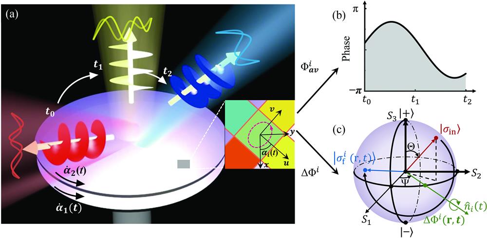
denotes the polarization state of the locally transmitted light [see Fig. 1(c)]. We note that the two angles unambiguously determine the polarization state of the transmitted light, with representing the ellipticity and dedicating the polar angle of polarization.
Figure 1.Schematic of the cascaded metasurface for dynamic wavefront control. (a) Sketch of the dynamic wavefront controlling process in which the direction and polarization state of the transmitted wave are evolving simultaneously over the time . The whole system is composed of multilayer metasurfaces with different phase distributions and angular speeds (where the indicates the layer number). The inset to panel (a) illustrates the local coordinate of a meta-atom and the global coordinate. Such a meta-atom can transmit a normally incident wave with (b) an averaged transmission phase and (c) different polarization states (described by the point on Poincaré’s sphere) evolving simultaneously over the time .
Equations (2)–(5) reveal that, as a light wave passes through the ’th layer at a point and time , the transmitted light gains an additional phase [see Fig. 1(b)] with the polarization state changed from to . Such a polarization-change can be understood as a rotation on Poincaré’s sphere by an angle with respect to the axis [see Eq. (5) and Fig. 1(c)], as rigorously shown in Ref. 45.
where denotes the total phase accumulated for light passing through the -layer system at a space-time point , and corresponds to a series of rotation operations on Poincaré’s sphere representing an effective manipulation of the polarization state of locally transmitted light.
Equation (6) indicates that, at a particular time , both the phase and polarization state of light passing through the device at a local point can be controlled [see Figs. 1(b) and 1(c)]. Therefore, by designing individual metasurfaces to exhibit appropriate phase distributions , we can offer the whole metadevice a desired time-dependent effective Jones-matrix represented by the total phase distribution and the polarization-manipulation operator , through controlling the orientation angles of different layers. According to Huygens’ principle, we can then dynamically reshape the wavefront and polarization distribution of the incident beam, through constructing and of the whole device in the desired manners.
with as the initial state. Rotating two layers at different speeds [see Fig. 2(e)] with being the time period of rotation, we employ Eqs. (2)–(6) to calculate the Jones-matrix properties [e.g., and ] of the whole metadevice at different time . To vividly illustrate the function of the polarization-manipulation operator , we assume that the incident beam takes a uniform left circular polarization (LCP) with and then compute the polarization distribution represented by determined by Eq. (6). Figure 2(c) shows the distributions of and the final polarization (represented by a series of ellipses) for the metadevice at different times . To illustrate the dynamic control functionality of the proposed device, we next employ a standard Green’s function approach to calculate the properties of light beams transmitted through the metadevice at different times , as the device is illuminated by a normally incident LCP light. Figure 2(d) shows the -field distributions of the transmitted beam on a plane above the metasurface at different times . Meanwhile, we also calculated the polarization states at different points on the transmitted wavefront [see those ellipses in Fig. 2(d)]. We found that beams transmitted through the device at different are all vectorial beams exhibiting vortex-like wavefronts with local polarization varying against the azimuthal angle, generally in consistency with the calculated phase and polarization distributions of the metadevice at different . However, we note that in certain cases the generated beams did not exhibit exactly the expected polarization distributions on the wavefront, since the proposed vectorial beams are not EM eigenstates in a vacuum, so that wave interferences can deteriorate the expected polarization distribution in propagations. Nevertheless, Fig. 2(d) clearly demonstrates that our proposed metadevice can indeed dynamically control the wavefront and polarization distribution of the transmitted beam.
Figure 2.Illustration of the dynamic controlling process. Two identical transparent metasurfaces with (a) phase distribution of and (b) phase distribution of are employed to illustrate the process. (c) The total phase of the device and (d) the scattered -field distributions calculated by the Green’s function approach for a transmitted beam at a distance above the surface for a normally incident LCP wave at five different time instants, with (e) the orientation angles evolving over time . Ellipses in (c) and (d) illustrate the polarization patterns at different locations inside the transmitted beam at a distance and above the surface.
We now employ the proposed strategy to realize dynamically tunable metadevices in the THz regime, starting from the meta-atom designs. To ensure that our metadevice exhibits a high working transparency, we choose to design a set of all-dielectric meta-atoms possessing high transmission efficiencies for THz waves. These meta-atoms can yield and values covering a wide range, enabling us to realize metadevices with designable functionalities for controlling both wavefront and polarization.
Figure 3(a) schematically shows the geometry of a typical meta-atom, which consists of two silicon posts exhibiting square and rectangular cross sections, respectively, deposited on different sides of a continuous silicon spacer. Whereas the silicon post on the bottom is mainly responsible generating the required due to its anisotropic cross section, the remaining parts in the meta-atom can help accumulate enough transmission phases to yield the desired . Therefore, tuning the lateral structures and heights of two silicon posts, we can design a set of meta-atoms yielding the desired values of and .
Figure 3.Meta-atom designs for both the phase and polarization manipulations. (a) Schematic of the designed meta-atom for independent phase and polarization controlling. FDTD-computed (b) transmission phase difference and (c) average transmission amplitude versus and for the bottom post under illuminations of - and -polarized beams, with fixed . (d) Simulated average transmission phase and (e) average transmission amplitude versus and for the whole meta-atom with after optimization of the bottom post. Other geometrical parameters of the meta-atoms are fixed as and .
We first show how to design the bottom silicon posts. For normally incident - and -polarized beams, we first investigate how the transmission characteristics [i.e., and ] of the bottom silicon post vary against two geometric parameters and , with other parameters fixed as , , and . Figures 3(b) and 3(c) show, respectively, the values of and computed by finite-difference time-domain (FDTD) simulations at 0.7 THz, as varying and . These two phase diagrams assist us in finding a series of highly transparent silicon posts exhibiting desired values of . We continue to examine the properties of the top silicon post. Now that the top post exhibits an isotropic cross section, it does not contribute to the transmission phase difference but only affects the average transmission phase of the whole meta-atom. Fixing the geometric parameters of the bottom post as those yielding , we employ FDTD simulations to calculate and of the whole meta-atom as varying and . As shown in Figs. 3(d) and 3(e), fixing height as , we find that changing can tune to vary in a full range. Following this strategy, we can quickly sort out the needed meta-atoms with desired and to form our metadevices.
4 Metadevice for Dynamic Beam-Steering
after passing through our device (see detailed derivations in Sec. II of the Supplemental Material).Here, the maximum polar angle is . As an illustration, we first consider the case that two speeds are . Put the corresponding relations in Eq. (9), we get Path I in Figs. 4(a) and 4(b) on which changes as a function of within a range of [0°, 41.2°] while stays unchanged [see Fig. 4(c)]. To illustrate a more complex beam-steering process, we change the two rotation speeds as and redo the analyses. We find this case corresponds to Path II in Figs. 4(a) and 4(b) on which both and change as functions of [see Fig. 4(d)]. Therefore, by setting to exhibit purposely designed time-dependent functions, we can offer the metadevice a desired beam-steering functionality in the way dictated by the relations.
Figure 4.Beam-steering process of transmitted waves along different paths. The phase diagrams of (a) polar angle and (b) azimuth angle as functions of and . The and change as functions of when the beam direction varies on (c) Path I and (d) Path II.
To realize such a metadevice, we follow the design strategy described in Sec. 3 to sort out 10 meta-atoms exhibiting transmission phases linearly increasing at a step of at frequency 0.7 THz, and then use them to construct our metadevice as shown in Fig. 5(a), where the two layers (named layer 1 and layer 2) are stacked along the direction. Here, each fabricated single-layer metasurface consists of a top layer and a bottom one. The inset to Fig. 5(a) depicts the side-view scanning-electron-microscope (SEM) images of the top and bottom layers of a single metasurface, while Figs. 5(b) and 5(c) show the top- and bottom-view SEM images of our fabricated metadevice (see fabrication method in Sec. III of the Supplemental Material). We note that silicon posts in all our adopted meta-atoms are of square cross sections since we do not need to control the local polarizations of the incident wave. Meanwhile, lateral sizes of top posts in these meta-atoms change significantly, generating different transmission phases (see geometric parameters in Sec. IV of the Supplemental Material).
Figure 5.Experimental and simulated results of the dynamic beam-steering metadevice. (a) Schematics of the metadevice consisting of two layers of transmissive metasurfaces aligned by a motorized rotation stage, as shown in the lower left inset. The upper left inset shows the side-view SEM pictures of a single metasurface, which consists of top and bottom layers. (b) Top-view (left) and (c) bottom-view (right) SEM pictures of the fabricated metadevice. (d) Schematics of the experimental setup to characterize the metadevice. (e) Experimental and (f) simulated far-field scattering power distributions as the metadevice is illuminated by an LCP light at 0.7 THz, as the metadevice evolves along Path I at different time instants. (g) Evolution of directions for transmitted waves on the sphere of direction as the metadevice moves along Path I and Path II, with solid line (star-symbols) denoting the simulated (experimental) results. Here, the blue region denotes the solid angle for beam-steering coverage.
With the fabricated metadevice at hand, we then experimentally demonstrate its beam-steering capabilities on incident THz waves as its two layers rotate at different speeds controlled by a motorized rotation stage, as shown in the lower left inset in Fig. 5(a) (see Sec. V of the Supplemental Material for more details). We first experimentally characterize the beam-steering capability of our metadevice with two layers rotating at speeds , which corresponds to the case of Path I as shown in Fig. 4(c) (see Sec. V of the Supplemental Material for details of experimental setup). Illuminating the metadevice by a normally incident LCP beam at 0.7 THz, we use a THz time-domain spectroscopy [THz-TDS; see Fig. 5(d)] system to measure the angular power distributions of the THz beams transmitted through the device at four different time instants [, and ]. In our experimental characterizations of the samples at different time instants, we fix the orientation angles of different layers at the values corresponding to the very time instants, to obtain stable results. Since the moving speeds of objects are much slower than light speed in vacuum, such a treatment does not bring any errors to the true performances of the device. The spacing distance between two layers is optimized as to ensure the stability of the whole system and obtain a tolerable efficiency (see Sec. VI of the Supplemental Material for the optimization of the spacing distance). Power distributions on the plane measured at different time instants clearly demonstrate that the incident THz beam has been efficiently redirected to an off-normal direction with polar angle changing from a maximum value of 41.2° to 0° as varies [Fig. 5(e)]. Full-wave simulated far-field scattering power distributions at different time instants [Fig. 5(f)] are in perfect agreement with the measured results, which further demonstrate the beam-steering effect. In our simulations, restricted by computational capabilities, we employed a metasurface with a diameter , much less than that () of the realistic sample, to obtain convergent results within a reasonable time. However, the computed scattering patterns thus exhibit inevitable side lobes caused by the edge effects [see Fig. 5(f)], which the measured patterns do not have [Fig. 5(e)] (see more details in Sec. VII of the Supplemental Material). From the measured/simulated scattering patterns, we identify the polar and azimuthal angles of the bending directions at different time instants and show how and vary against in the “sphere of direction,” as illustrated by the Path I in Fig. 5(g). Obviously, the measured and simulated and relations are in perfect agreement with the theoretical prediction [i.e., Path I in Fig. 4(c)].
We continue to demonstrate the beam-steering performance of the metadevice, setting the rotation speeds of two layers as . As analyzed before, our metadevice rotating in such a mode can redirect the normally incident light to scan on Path II (see Fig. 4) where both and vary as functions of . We identify the directions of the THz beams (represented by the and angles) transmitted through our metadevice at different time instants [, and ] from both the measurements and simulations and depict them on the sphere of direction in Fig. 5(g). Both the measurements and simulations show that the working efficiency of our metadevice is around 50% (see details in Sec. VIII of the Supplemental Material). The nice agreements among the theoretical, simulated, and measured results have unambiguously demonstrated the expected beam-steering capability of the metadevice (see Sec. IX and Sec. X of the Supplemental Material for more details on working bandwidth and angular dependence of the metadevice).
5 Metadevice for Dynamic Beam-Steering and Polarization Control
Similar to the metadevice studied in last section, this device can also redirect a normally incident light to an off-normal direction with a tangential wave-vector . However, a crucial difference is that present device can further control the polarization of the light beam through the operator . As discussed in Ref. 45, the operation enabled by can be viewed as two successive rotations of Poincaré’s sphere by an angle of through the axes and . Figure 6(a) contains an example showing how the two successive rotations work, assuming that the incident light takes LCP [i.e., ] and . After the incident light transmits through the first metasurface, light polarization changes from the initial one (i.e., the north pole on Poincaré’s sphere) to (located on the equator of Poincaré’s sphere) through a rotation operation along the axis by an angle of . Then, after the light beam passes through the second layer, its polarization further changes from to the final state , through another rotation operation along the axis with an angle . As the orientation angles of two layers vary in the range , the intermediate state can cover the whole equator, while the final state can cover the entirety of Poincaré’s sphere [see Fig. 6(a)]. In principle, via choosing the appropriate value and functions, one can realize any polarization manipulation of transmitted light in a desired way.
Figure 6.Experimental and simulated results of the metadevice for simultaneous beam-steering and polarization manipulation. (a) Rotation operations on Poincaré’s sphere for an LCP incident wave passing through the two-layer cascaded metasurfaces. (b) The phase distribution of and of two identical anisotropic metasurfaces. (c) SEM images of the top and bottom of the designed meta-atoms. The evolution of (d) directions on a sphere of direction and (e) the polarization states on Poincaré’s sphere for transmitted waves varying over time, where the blue region denotes the beam-steering and polarization coverage and the star-symbols represent the and polarization state at three different time instants []. (f)–(h) Experimental (blue circles) and simulated (blue line) far-field scattering patterns (left panel) and polarization states (right panel) of the transmitted wave of three certain time instants.
We design/fabricate a metadevice with and [see Fig. 6(b)] and experimentally demonstrate its wave-manipulation functionality at the frequency of 0.7 THz. We follow the design strategy described in Sec. 3 to sort out 10 meta-atoms (see Sec. IV of the Supplemental Material for their geometric parameters) with the cross-polarization phase difference and the linearly increasing average phase with a step of and use them to construct a metasurface, and in turn, our metadevice. Figure 6(c) show the top- and bottom-view SEM images of our fabricated metadevice. Different from the metadevice studied in last section, in this device the bottom silicon posts are of rectangular cross sections, which are responsible for generating the desired transmission phase differences for controlling light polarizations.
We numerically illustrate the performance of this metadevice. Assuming that two layers rotate at different speeds , we employ FDTD simulations to study the beam-steering properties of the metadevice, as it is illuminated by a normally incident LCP beam at 0.7 THz. Figures 6(d) and 6(e) show, respectively, how the propagation direction and polarization state of the transmitted beam evolve as varies over a time period, obtained by theoretical predictions based on Eq. (11). We find that our metadevice can not only dynamically redirect a normally incident beam to an off-normal direction but also modulate the polarization state of the beam simultaneously. We note that the path corresponding to is a closed loop, which means that the system moves back to the origin point (on both the sphere of and Poincaré’s sphere) after a time period . In fact, paths with any kinds of time evolutions can be designed in our framework. For example, one can connect two different states on Poincaré’s sphere with many predesigned paths with different time evolutions and can also realize a closed loop with a time period of (e.g., ).
We next experimentally characterize the beam-steering functionality of this metadevice with two layers rotating at speeds . Illuminating the metadevice by a normally incident LCP beam at 0.7 THz, we use the THz-TDS to measure the angular power distributions of the transmitted waves at three different time instants [, , and ], respectively. Measured power distributions [denoted by hollow circles shown in the left-hand panels of Figs. 6(f)–6(h)] demonstrate clearly that our metadevice can indeed redirect the normally incident beam to a particular off-normal direction at different times. Simulated far-field scattering patterns [solid lines in Figs. 6(f)–6(h)] of the transmitted wave are in nice agreement with the measured results. The working efficiency of the device is found as (see details in Sec. VIII of the Supplemental Material).
Finally, we experimentally characterize the polarization states of the deflected beams at different time instants. Via rotating a linearly polarized receiver, we use the TDS to measure the amplitudes and phases of transmitted signals polarized along two orthogonal directions, and in turn, unambiguously determine the polarization states of the transmitted beams (see details in Sec. XI of the Supplemental Material). Experimentally determined polarization patterns of THz beams transmitted through the device at three different time instants are shown as open circles in the right-hand panels of Figs. 6(f)–6(h), compared with those obtained directly by Eq. (11) (dashed lines) and by numerical simulations of the transmitted light (solid lines). Reasonable agreement is noted among these results. In particular, we find that the polarization of transmitted beam changes from a CP, to an elliptical one, and finally to an LP, as time increases [see the right-hand panels of Figs. 6(f)–6(h)].
6 Conclusions and Discussions
We propose an alternative approach to dynamically controlling the wavefront and polarization of a light beam without using active elements for local tuning, and experimentally demonstrate the idea in the THz regime. The proposed metadevice consists of a few layers of transmissive metasurfaces exhibiting certain phase profiles. Rotating different layers with different speeds, we show that the whole device can exhibit a time-dependent Jones-matrix, which helps with controlling the light beam dynamically in terms of wavefront and polarization. Two all-dielectric metadevices are designed, fabricated, and experimentally characterized. The first one can efficiently redirect a normally incident THz beam to off-normal directions covering a wide solid-angle range, while the second can dynamically control both the wavefront and polarization state of a THz beam. Both devices exhibit robust performances against varying the size of each layer, the spacing distance, and the misalignment between layers.
Our results pave the way to achieving dynamic control of THz beams, which may inspire many future works (e.g., THz radar, bio- and chemical sensing and imaging, etc.). Through elaborately designing each single-layer metasurface, one can also realize other metadevices exhibiting different wave-manipulation functionalities (e.g., cooperative beamforming and beam-steering; see more details in Sec. XII of the Supplemental Material). Wave-manipulation capabilities of the proposed metadevices can be further enriched through adding more layers of metasurfaces. For example, we have designed a four-layer metadevice to independently control the direction and polarization of the transmitted beam (see more details in Sec. XIII of the Supplemental Material). However, we also note that adding more layers will enhance the cross-talking between different layers and decrease the efficiency for the metadevices, which is the inevitable price to pay. We expect more applications of our proposed strategy.