• Laser & Optoelectronics Progress
  • Vol. 56, Issue 18, 180301 (2019)
Zhijing Yu1, Xin Li1, Yanling Li1, Zechuan Li2, and Jingchang Zhuge1、*
Author Affiliations
  • 1 Electronic Information and Automation College, Civil Aviation University of China, Tianjin 300300, China
  • 2 Aeronautical Engineering College, Civil Aviation University of China, Tianjin 300300, China
  • show less
    DOI: 10.3788/LOP56.180301 Cite this Article Set citation alerts
    Zhijing Yu, Xin Li, Yanling Li, Zechuan Li, Jingchang Zhuge. Minor Damage Location Method for Aircraft Skins Based on Marked Honeycomb Model[J]. Laser & Optoelectronics Progress, 2019, 56(18): 180301 Copy Citation Text show less
    Basic point transfer model of honeycomb model
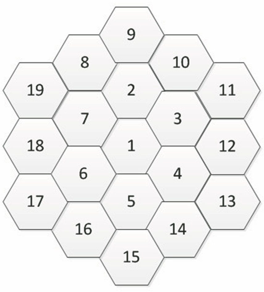
    Fig. 1. Basic point transfer model of honeycomb model
    RRT reflective marks
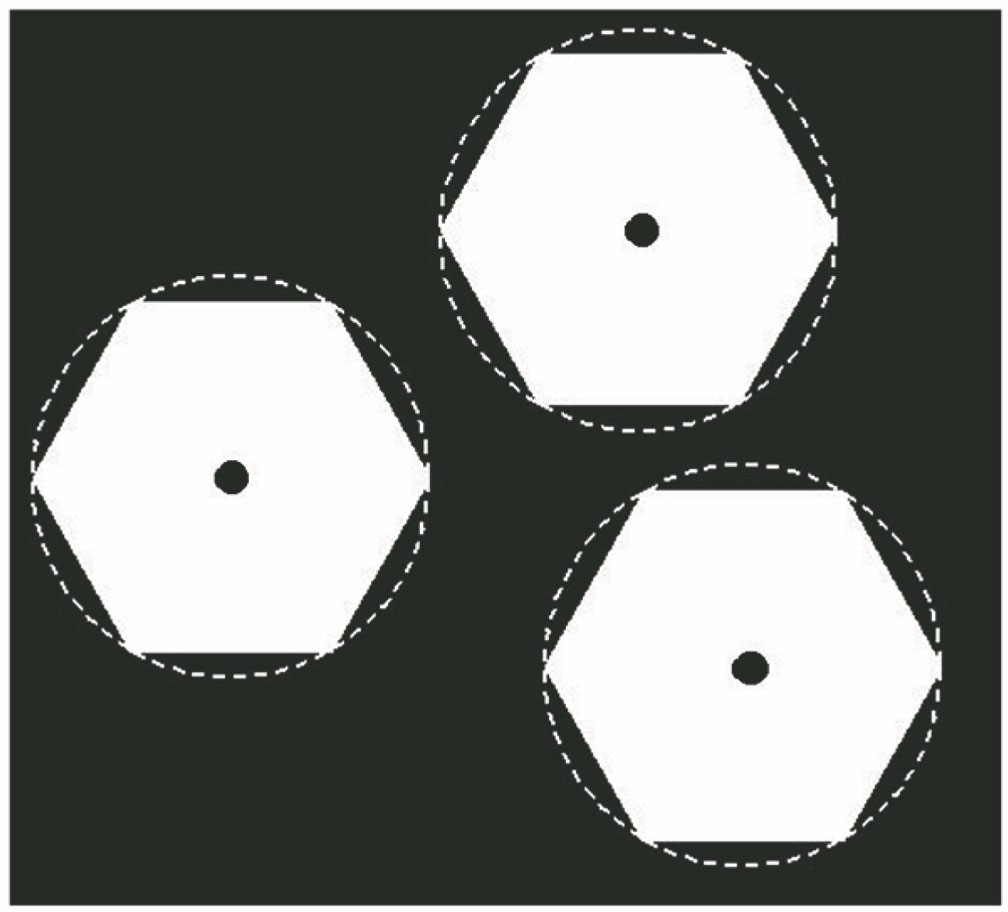
    Fig. 2. RRT reflective marks
    Pixel edge of feature control point
    Fig. 3. Pixel edge of feature control point
    Radial grayscale gradient
    Fig. 4. Radial grayscale gradient
    Subpixel edge point
    Fig. 5. Subpixel edge point
    Diagram of projection of circular inscribed hexagon
    Fig. 6. Diagram of projection of circular inscribed hexagon
    Cross ratio invariance principle in hexagon
    Fig. 7. Cross ratio invariance principle in hexagon
    Diagram of experimental device
    Fig. 8. Diagram of experimental device
    Schematic of experimental process
    Fig. 9. Schematic of experimental process
    Control point layout model of damaged skin
    Fig. 10. Control point layout model of damaged skin
    Damage to surface of aircraft skin. (a) Normal skin; (b) crack; (c) corrosion; (d) strike; (e) scratch
    Fig. 11. Damage to surface of aircraft skin. (a) Normal skin; (b) crack; (c) corrosion; (d) strike; (e) scratch
    3×3 template images after adaptive median filtering. (a) Normal; (b) crack; (c) corrosion; (d) strike; (e) scratch
    Fig. 12. 3×3 template images after adaptive median filtering. (a) Normal; (b) crack; (c) corrosion; (d) strike; (e) scratch
    Error values and time consumptions of three algorithms. (a) Error in image; (b) time consumption; (c) relative truth error
    Fig. 13. Error values and time consumptions of three algorithms. (a) Error in image; (b) time consumption; (c) relative truth error
    Experimental groupPositioning methodData resultTheoretical optimal value
    1Honeycomb model location method(1157.38,1349.27)(1156.95,1348.94)(1157.73,1350.12)(1158.08,1349.23)(1157.64,1348.75)
    Method in Ref. [11](581.82,349.36)(582.24,350.03)(581.43,348.97)(581.12,348.62)(582.42,350.37)
    Method in Ref. [9](217.60,145.39)(216.92,144.88)(217.05,144.98)(217.83,145.64)(218.85,146.38)
    2Honeycomb model location method(597.60,344.36)(597.82,344.57)(598.05,343.98)(596.89,345.35)(597.64,344.25)
    Method in Ref. [11](1851.03,1247.87)(1851.37,1248.24)(1850.72,1247.48)(1851.65,1248.56)(1852.76,1241.28)
    Method in Ref. [9](654.78,864.63)(655.21,865.02)(655.68,865.43)(654.38,864.19)(665.68,875.13)
    3Honeycomb model location method(800.16,675.26)(799.89,675.03)(799.60,674.69)(801.75,675.57)(800.37,674.96)
    Method in Ref. [11](514.76,483.87)(515.09,484.23)(515.46,484.61)(515.78,484.97)(525.09,481.23)
    Method in Ref. [9](1264.53,1027.86)(1264.87,1028.22)(1265.33,1028.76)(1265.69,1029.14)(1267.74,1030.12)
    4Honeycomb model location method(1697.61,1144.36)(1698.10,1144.77)(1697.32,1145.16)(1696.95,1143.84)(1697.43,1144.27)
    Method in Ref. [11](1456.47,987.39)(1456.68,987.63)(1456.89,987.87)(1457.12,988.23)(1466.18,980.63)
    Method in Ref. [9](1733.64,1368.59)(1734.12,1368.93)(1734.44,1369.29)(1733.23,1368.27)(1745.22,1370.47)
    Table 1. Center coordinate results of four groups of control points under three different methodspixel
    Zhijing Yu, Xin Li, Yanling Li, Zechuan Li, Jingchang Zhuge. Minor Damage Location Method for Aircraft Skins Based on Marked Honeycomb Model[J]. Laser & Optoelectronics Progress, 2019, 56(18): 180301
    Download Citation