• Matter and Radiation at Extremes
  • Vol. 7, Issue 6, 065901 (2022)
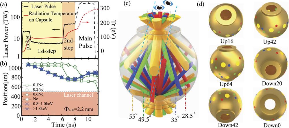
Yao-Hua Chen1, Zhichao Li2, Hui Cao1, Kaiqiang Pan2, Sanwei Li2, Xufei Xie2, Bo Deng2, Qiangqiang Wang2, Zhurong Cao2, Lifei Hou2, Xingsen Che2, Pin Yang2, Yingjie Li2, Xiaoan He2, Tao Xu2, Yonggang Liu2, Yulong Li2, Xiangming Liu2, Haijun Zhang2, Wei Zhang2, Baibin Jiang2, Jun Xie2, Wei Zhou2, Xiaoxia Huang2, Wen Yi Huo1, Guoli Ren1, Kai Li1, Xudeng Hang1, Shu Li1, Chuanlei Zhai1, Jie Liu3、4, Shiyang Zou1, Yongkun Ding1、4, and Ke Lan1、4、a)
Author Affiliations
  • 1Institute of Applied Physics and Computational Mathematics, Beijing 100094, China
  • 2Research Center of Laser Fusion, China Academy of Engineering Physics, Mianyang 621900, China
  • 3Graduate School, China Academy of Engineering Physics, Beijing, China
  • 4HEDPS, Center for Applied Physics and Technology, and College of Engineering, Peking University, Beijing 100871, China
  • show less
    DOI: 10.1063/5.0102447 Cite this Article
    Yao-Hua Chen, Zhichao Li, Hui Cao, Kaiqiang Pan, Sanwei Li, Xufei Xie, Bo Deng, Qiangqiang Wang, Zhurong Cao, Lifei Hou, Xingsen Che, Pin Yang, Yingjie Li, Xiaoan He, Tao Xu, Yonggang Liu, Yulong Li, Xiangming Liu, Haijun Zhang, Wei Zhang, Baibin Jiang, Jun Xie, Wei Zhou, Xiaoxia Huang, Wen Yi Huo, Guoli Ren, Kai Li, Xudeng Hang, Shu Li, Chuanlei Zhai, Jie Liu, Shiyang Zou, Yongkun Ding, Ke Lan. Determination of laser entrance hole size for ignition-scale octahedral spherical hohlraums[J]. Matter and Radiation at Extremes, 2022, 7(6): 065901 Copy Citation Text show less
    (a) Required Tr (red curve) on the capsule of a high-foot scheme and the derived laser pulse (black curve) from 2D simulations for a 2-LEH spherical hohlraum with ΦH = 8.8 mm and ΦLEH = 2.2 mm. Only the prepulse (black solid curve) is considered in this experiment. (b) Post-processed time-dependent positions of plasma interface with electron density Ne = 0.1Nc, 0.2Nc, 0.6Nc, and Nc and positions of 50% peak x-ray emissions with energies between 0.8 and 1 keV or above 1.8 keV. The pink region is the laser channel. (c) Schematic of laser beam configuration and ignition-scale 2-LEH spherical hohlraum. The laser beams at 55° (orange) have a 1 mm diameter round shape at the LEH, and those at other angles have a 0.5 mm diameter. (d) Initial fields of view of the six flat-response x-ray detectors (FXRDs) and filtered M-band x-ray detectors (MXRDs), with the spots on the wall representing the laser depositions.
    Fig. 1. (a) Required Tr (red curve) on the capsule of a high-foot scheme and the derived laser pulse (black curve) from 2D simulations for a 2-LEH spherical hohlraum with ΦH = 8.8 mm and ΦLEH = 2.2 mm. Only the prepulse (black solid curve) is considered in this experiment. (b) Post-processed time-dependent positions of plasma interface with electron density Ne = 0.1Nc, 0.2Nc, 0.6Nc, and Nc and positions of 50% peak x-ray emissions with energies between 0.8 and 1 keV or above 1.8 keV. The pink region is the laser channel. (c) Schematic of laser beam configuration and ignition-scale 2-LEH spherical hohlraum. The laser beams at 55° (orange) have a 1 mm diameter round shape at the LEH, and those at other angles have a 0.5 mm diameter. (d) Initial fields of view of the six flat-response x-ray detectors (FXRDs) and filtered M-band x-ray detectors (MXRDs), with the spots on the wall representing the laser depositions.
    (Left) Time-resolved raw images from an x-ray framing camera (XFC) at four different times and for two x-ray energy ranges of 0.8–1 and 2–3 keV for shot SGIII20170323148 with 1.4 mm diameter LEHs (upper) and shot SGIII20170324150 with 2 mm diameter LEHs (lower). (Middle) Drive laser power (light cyan dashed curve) and Tr (solid curves) with an error bar of 3% for shots SGIII20170323148 (upper) and SGIII20170324150 (lower). The small images match those on the left, except that the upper ones at 2.5 and 5.5 ns are for shot SGIII20170323149. (Right) Time-dependent LEH radius, defined as the half peak width of x-ray emissions of 0.8–1 keV, from XFC images (symbols with error bars of ±75 µm) and from post-shot 2D simulation (orange solid line) for shots with 1.4 mm diameter LEHs (upper) and 2 mm diameter LEHs (lower), with the red dashed line indicating the laser beam size. The mode 1 azimuthal asymmetry of the XFC images is due to the axis deviation between each pinhole and the XFC and to the axis deviation between the XFC and the target, which are considered in the error bars.
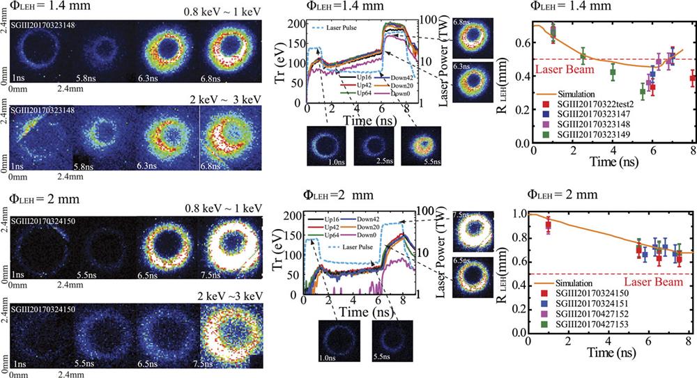
    Fig. 2. (Left) Time-resolved raw images from an x-ray framing camera (XFC) at four different times and for two x-ray energy ranges of 0.8–1 and 2–3 keV for shot SGIII20170323148 with 1.4 mm diameter LEHs (upper) and shot SGIII20170324150 with 2 mm diameter LEHs (lower). (Middle) Drive laser power (light cyan dashed curve) and Tr (solid curves) with an error bar of 3% for shots SGIII20170323148 (upper) and SGIII20170324150 (lower). The small images match those on the left, except that the upper ones at 2.5 and 5.5 ns are for shot SGIII20170323149. (Right) Time-dependent LEH radius, defined as the half peak width of x-ray emissions of 0.8–1 keV, from XFC images (symbols with error bars of ±75 µm) and from post-shot 2D simulation (orange solid line) for shots with 1.4 mm diameter LEHs (upper) and 2 mm diameter LEHs (lower), with the red dashed line indicating the laser beam size. The mode 1 azimuthal asymmetry of the XFC images is due to the axis deviation between each pinhole and the XFC and to the axis deviation between the XFC and the target, which are considered in the error bars.
    (a) Time-integrated x-ray image at 2–3 keV observed by the pinhole camera at 16° from the upper side and (b) its field of view for shot SGIII20170323149 with 1.4 mm diameter LEHs. (c) and (d) Corresponding image and field of view for shot SGIII20170324150 with 2 mm diameter LEHs. The red dashed circle is the LEH edge and the yellow dashed circle is the outer boundary of the 1 mm diameter laser beam. Note that the size scales of the two images are different.
    Fig. 3. (a) Time-integrated x-ray image at 2–3 keV observed by the pinhole camera at 16° from the upper side and (b) its field of view for shot SGIII20170323149 with 1.4 mm diameter LEHs. (c) and (d) Corresponding image and field of view for shot SGIII20170324150 with 2 mm diameter LEHs. The red dashed circle is the LEH edge and the yellow dashed circle is the outer boundary of the 1 mm diameter laser beam. Note that the size scales of the two images are different.
    Temporal behaviors of the M-band fluxes measured by the six MXRDs for shots with ΦLEH = 1.4, 1.6, 1.8, 2, and 2.4 mm, with an error bar of 10%. The burrs on the curves are due to diagnostic noise at low fluxes. Note that the flux scale for ΦLEH = 1.4 mm is different from the others.
    Fig. 4. Temporal behaviors of the M-band fluxes measured by the six MXRDs for shots with ΦLEH = 1.4, 1.6, 1.8, 2, and 2.4 mm, with an error bar of 10%. The burrs on the curves are due to diagnostic noise at low fluxes. Note that the flux scale for ΦLEH = 1.4 mm is different from the others.
    Temporal behavior of Tr (solid curves) derived using the measured fluxes from six FXRDs for shots with ΦLEH = 1.4, 1.6, 1.8, 2, and 2.4 mm. The laser power (light gray dashed lines) is shown for reference.
    Fig. 5. Temporal behavior of Tr (solid curves) derived using the measured fluxes from six FXRDs for shots with ΦLEH = 1.4, 1.6, 1.8, 2, and 2.4 mm. The laser power (light gray dashed lines) is shown for reference.
    ΦLEH (mm)1.622.42.83.23.6
    C401.7 × 10−32.5 × 10−33.4 × 10−35.1 × 10−37.1 × 10−39.2 × 10⁻³
    C441.0 × 10−31.5 × 10−32.1 × 10−33.0 × 10−34.2 × 10−35.5 × 10⁻³
    C601.6 × 10−61.2 × 10−52.8 × 10−54.8 × 10−56.7 × 10−58.4 × 10⁻⁵
    C641.7 × 10−62.4 × 10−55.3 × 10−59.0 × 10−51.2 × 10−41.6 × 10⁻⁴
    C808.6 × 10−49.6 × 10−41.0 × 10−31.0 × 10−38.1 × 10−44.2 × 10⁻⁴
    C843.2 × 10−43.6 × 10−43.9 × 10−43.8 × 10−43.1 × 10−41.6 × 10⁻⁴
    C884.9 × 10−45.5 × 10−45.9 × 10−45.8 × 10−44.6 × 10−42.4 × 10⁻⁴
    ϵrms2.6 × 10−33.5 × 10−34.7 × 10−36.8 × 10−39.3 × 10−31.2 × 10⁻²
    EaL (MJ)1.191.381.611.882.192.54
    EL (MJ)1.321.531.792.082.432.82
    LEH loss (MJ)0.400.630.911.241.622.05
    Table 1. Clm, ϵrms, EaL, EL, and LEH loss of an octahedral hohlraum with RH = 4RC for the CH Rev5 capsule, with ΦLEH varying from 1.6 to 3.6 mm. Here, the LEH loss is the amount of input laser energy lost via the LEHs and is given by Eloss/ηaLηLX. In each case, the input laser energy EL is chosen to give a radiation temperature of 300 eV.
    ΦLEH (mm)1.622.42.83.23.6
    C403.9 × 10−55.6 × 10−57.7 × 10−51.0 × 10−41.3 × 10−41.8 × 10⁻⁴
    C442.4 × 10−53.4 × 10−54.7 × 10−56.1 × 10−58.0 × 10−51.1 × 10⁻⁴
    C601.1 × 10−61.5 × 10−53.3 × 10−55.1 × 10−57.1 × 10−59.7 × 10⁻⁵
    C641.1 × 10−62.9 × 10−56.3 × 10−59.7 × 10−51.4 × 10−41.8 × 10⁻⁴
    C802.3 × 10−42.7 × 10−43.1 × 10−43.3 × 10−43.4 × 10−43.2 × 10⁻⁴
    C848.8 × 10−51.0 × 10−41.2 × 10−41.2 × 10−41.3 × 10−41.2 × 10⁻⁴
    C881.3 × 10−41.6 × 10−41.8 × 10−41.9 × 10−41.9 × 10−41.8 × 10⁻⁴
    ϵrms3.4 × 10−43.9 × 10−44.5 × 10−45.3 × 10−47.2 × 10−46.0 × 10⁻⁴
    EaL (MJ)1.571.761.982.252.562.92
    EL (MJ)1.741.952.212.502.853.24
    LEH loss (MJ)0.400.630.911.241.622.05
    Table 2. Clm, ϵrms, EaL, EL, and LEH loss of an octahedral hohlraum with RH = 5RC for the CH Rev5 capsule, with ΦLEH varying from 1.6 to 3.6 mm. The LEH loss is the same as in Table I, and is given here for comparison with EL.
    Yao-Hua Chen, Zhichao Li, Hui Cao, Kaiqiang Pan, Sanwei Li, Xufei Xie, Bo Deng, Qiangqiang Wang, Zhurong Cao, Lifei Hou, Xingsen Che, Pin Yang, Yingjie Li, Xiaoan He, Tao Xu, Yonggang Liu, Yulong Li, Xiangming Liu, Haijun Zhang, Wei Zhang, Baibin Jiang, Jun Xie, Wei Zhou, Xiaoxia Huang, Wen Yi Huo, Guoli Ren, Kai Li, Xudeng Hang, Shu Li, Chuanlei Zhai, Jie Liu, Shiyang Zou, Yongkun Ding, Ke Lan. Determination of laser entrance hole size for ignition-scale octahedral spherical hohlraums[J]. Matter and Radiation at Extremes, 2022, 7(6): 065901
    Download Citation