
Yao-Hua Chen, Zhichao Li, Hui Cao, Kaiqiang Pan, Sanwei Li, Xufei Xie, Bo Deng, Qiangqiang Wang, Zhurong Cao, Lifei Hou, Xingsen Che, Pin Yang, Yingjie Li, Xiaoan He, Tao Xu, Yonggang Liu, Yulong Li, Xiangming Liu, Haijun Zhang, Wei Zhang, Baibin Jiang, Jun Xie, Wei Zhou, Xiaoxia Huang, Wen Yi Huo, Guoli Ren, Kai Li, Xudeng Hang, Shu Li, Chuanlei Zhai, Jie Liu, Shiyang Zou, Yongkun Ding, Ke Lan. Determination of laser entrance hole size for ignition-scale octahedral spherical hohlraums[J]. Matter and Radiation at Extremes, 2022, 7(6): 065901
- Matter and Radiation at Extremes
- Vol. 7, Issue 6, 065901 (2022)
Abstract
I. INTRODUCTION
Achieving ignition is the major step on the path to controlled nuclear fusion energy, which has been a quest of scientists worldwide for more than a half a century.1–3 Recently, the marvelous 1.37 MJ nuclear yield4–7 of the National Ignition Facility (NIF)8–10 is a clue that access to high fusion yields via indirect drive inertial confinement fusion may be attainable in the future. However, there are still major obstacles at the NIF to obtaining a predictable and reproducible fusion gain, such as irradiation asymmetry,11–13 laser plasma instabilities (LPIs),14–16 and hydrodynamic instabilities,2,17,18 all of which are strongly connected with the hohlraum configuration and laser arrangement. The recently proposed octahedral spherical hohlraum19–22 (hereinafter referred to simply as the octahedral hohlraum) with a single laser injection angle of 55° is an attractive concept for achieving a stable fusion gain at an upgraded facility23 and can provide a high-symmetry drive on the capsule without any symmetry tuning. Experimental campaigns started in 2014 at the SG laser facility,24 addressing the key issues regarding the design,25–28 energetics,29–31 and proof-of-concept32 of the octahedral hohlraum. This novel approach has attracted broad interest in the fusion community.33–39
In contrast to cylindrical hohlraums with their two laser entrance holes (LEHs),2,40–43 an octahedral hohlraum has six LEHs, and so LEH size can be a critical issue, given the laser energies that are available at present. As an example, we consider an Au octahedral hohlraum for the CH Rev5 ignition capsule44 of the NIF, which can produce a clean one-dimensional (1D) yield 17.5 MJ according to Ref. 44. We calculate below the required laser energy and asymmetry of an octahedral hohlraum for this capsule. The absorbed laser energy EaL of the hohlraum can be calculated using the energy balance2,45,46
To calculate the radiation asymmetry on the capsule, we expand the radiation flux on capsule surface as
In Tables I and II, we present Clm, ϵrms, EaL, EL, and the radiation loss from LEHs for the CH Rev5 capsule inside octahedral hohlraums with ΦH/ΦC = 4 and 5, respectively, at ΦLEH = 1.6–3.6 mm. Here, ϵrms is the overall %rms including all modes.3 We take the initial radii of the hohlraum and capsule in the calculation. It can be seen that Y2m and Ylm are absent for all odd l, because they are naturally zero in the octahedral geometry. For ΦH/ΦC = 4, Y40 dominates the asymmetry and increases with increasing ΦLEH, with Y40 < 1% at ΦLEH ≤ 3.6 mm. For ΦH/ΦC = 5, termed the golden radius ratio in Ref. 20, the asymmetry is dominated by Y80, with Y80 < 3.4 × 10⁻⁴ for all ΦLEH. Thus, the asymmetry in all cases easily meets the ignition criterion of 1%.2 However, EaL is sensitive to ΦLEH, because the six LEHs of larger size can lead to a remarkably high radiation energy loss. From Tables I and II, it can be seen that changing the LEH size makes a significant difference to the laser energy required. The calculations show that the energy requirement exceeds the present laser energy of 2 MJ at the NIF for ΦLEH > 2.7 mm at ΦH = 8.864 mm, and for ΦLEH > 2.1 mm at ΦH = 11.08 mm. Obviously, the upper limit of LEH size is restricted by the available laser energy. It seems that a smaller LEH should decrease EaL; however, this is under the assumption that all laser beams can be fully injected into the hohlraum. If an LEH is small enough that some of the laser energy is blocked outside the hohlraum, greater laser energy will be needed to generate the required radiation temperature inside the hohlraum. Thus, the optimum LEH size should be a trade-off between clearance for the laser beams and available laser energy.
| ΦLEH (mm) | 1.6 | 2 | 2.4 | 2.8 | 3.2 | 3.6 |
|---|---|---|---|---|---|---|
| C40 | 1.7 × 10⁻³ | 2.5 × 10⁻³ | 3.4 × 10⁻³ | 5.1 × 10⁻³ | 7.1 × 10⁻³ | 9.2 × 10⁻³ |
| C44 | 1.0 × 10⁻³ | 1.5 × 10⁻³ | 2.1 × 10⁻³ | 3.0 × 10⁻³ | 4.2 × 10⁻³ | 5.5 × 10⁻³ |
| C60 | 1.6 × 10⁻⁶ | 1.2 × 10⁻⁵ | 2.8 × 10⁻⁵ | 4.8 × 10⁻⁵ | 6.7 × 10⁻⁵ | 8.4 × 10⁻⁵ |
| C64 | 1.7 × 10⁻⁶ | 2.4 × 10⁻⁵ | 5.3 × 10⁻⁵ | 9.0 × 10⁻⁵ | 1.2 × 10⁻⁴ | 1.6 × 10⁻⁴ |
| C80 | 8.6 × 10⁻⁴ | 9.6 × 10⁻⁴ | 1.0 × 10⁻³ | 1.0 × 10⁻³ | 8.1 × 10⁻⁴ | 4.2 × 10⁻⁴ |
| C84 | 3.2 × 10⁻⁴ | 3.6 × 10⁻⁴ | 3.9 × 10⁻⁴ | 3.8 × 10⁻⁴ | 3.1 × 10⁻⁴ | 1.6 × 10⁻⁴ |
| C88 | 4.9 × 10⁻⁴ | 5.5 × 10⁻⁴ | 5.9 × 10⁻⁴ | 5.8 × 10⁻⁴ | 4.6 × 10⁻⁴ | 2.4 × 10⁻⁴ |
| ϵrms | 2.6 × 10⁻³ | 3.5 × 10⁻³ | 4.7 × 10⁻³ | 6.8 × 10⁻³ | 9.3 × 10⁻³ | 1.2 × 10⁻² |
| EaL (MJ) | 1.19 | 1.38 | 1.61 | 1.88 | 2.19 | 2.54 |
| EL (MJ) | 1.32 | 1.53 | 1.79 | 2.08 | 2.43 | 2.82 |
| LEH loss (MJ) | 0.40 | 0.63 | 0.91 | 1.24 | 1.62 | 2.05 |
Table 1. Clm, ϵrms, EaL, EL, and LEH loss of an octahedral hohlraum with RH = 4RC for the CH Rev5 capsule, with ΦLEH varying from 1.6 to 3.6 mm. Here, the LEH loss is the amount of input laser energy lost via the LEHs and is given by Eloss/ηaLηLX. In each case, the input laser energy EL is chosen to give a radiation temperature of 300 eV.
| ΦLEH (mm) | 1.6 | 2 | 2.4 | 2.8 | 3.2 | 3.6 |
|---|---|---|---|---|---|---|
| C40 | 3.9 × 10⁻⁵ | 5.6 × 10⁻⁵ | 7.7 × 10⁻⁵ | 1.0 × 10⁻⁴ | 1.3 × 10⁻⁴ | 1.8 × 10⁻⁴ |
| C44 | 2.4 × 10⁻⁵ | 3.4 × 10⁻⁵ | 4.7 × 10⁻⁵ | 6.1 × 10⁻⁵ | 8.0 × 10⁻⁵ | 1.1 × 10⁻⁴ |
| C60 | 1.1 × 10⁻⁶ | 1.5 × 10⁻⁵ | 3.3 × 10⁻⁵ | 5.1 × 10⁻⁵ | 7.1 × 10⁻⁵ | 9.7 × 10⁻⁵ |
| C64 | 1.1 × 10⁻⁶ | 2.9 × 10⁻⁵ | 6.3 × 10⁻⁵ | 9.7 × 10⁻⁵ | 1.4 × 10⁻⁴ | 1.8 × 10⁻⁴ |
| C80 | 2.3 × 10⁻⁴ | 2.7 × 10⁻⁴ | 3.1 × 10⁻⁴ | 3.3 × 10⁻⁴ | 3.4 × 10⁻⁴ | 3.2 × 10⁻⁴ |
| C84 | 8.8 × 10⁻⁵ | 1.0 × 10⁻⁴ | 1.2 × 10⁻⁴ | 1.2 × 10⁻⁴ | 1.3 × 10⁻⁴ | 1.2 × 10⁻⁴ |
| C88 | 1.3 × 10⁻⁴ | 1.6 × 10⁻⁴ | 1.8 × 10⁻⁴ | 1.9 × 10⁻⁴ | 1.9 × 10⁻⁴ | 1.8 × 10⁻⁴ |
| ϵrms | 3.4 × 10⁻⁴ | 3.9 × 10⁻⁴ | 4.5 × 10⁻⁴ | 5.3 × 10⁻⁴ | 7.2 × 10⁻⁴ | 6.0 × 10⁻⁴ |
| EaL (MJ) | 1.57 | 1.76 | 1.98 | 2.25 | 2.56 | 2.92 |
| EL (MJ) | 1.74 | 1.95 | 2.21 | 2.50 | 2.85 | 3.24 |
| LEH loss (MJ) | 0.40 | 0.63 | 0.91 | 1.24 | 1.62 | 2.05 |
Table 2. Clm, ϵrms, EaL, EL, and LEH loss of an octahedral hohlraum with RH = 5RC for the CH Rev5 capsule, with ΦLEH varying from 1.6 to 3.6 mm. The LEH loss is the same as in Table
To have sufficient LEH clearance for the laser beams, the lower limit of LEH size is determined by three factors: (1) the focal spot size of the laser beam at the LEH, (2) the LEH closure caused by radiation, and (3) laser pointing error. Again considering the CH Rev5 capsule, the LEH closure under a 300 eV ignition pulse is about 0.29 mm according to our 1D multigroup radiation transfer hydrodynamic code RDMG.49–51 Taking the pointing error as 0.08 mm for a laser beam of round shape with 1.2 mm diameter at the LEH, we estimate a LEH diameter ΦLEH ∼ 2 mm.21 Detail 2D simulations using LARED-Integration have shown that a value of ΦLEH = 2.4 mm can leave enough room52 for this ignition target design. However, owing to the uncertainties in the simulation,53 the LEH size should be determined with convincing experimental evidence before pursuing an ignition-scale laser system based on the octahedral hohlraum. Nevertheless, it remains a challenging task to determine the LEH size of an ignition target at a small-scale laser facility, because it is impossible to create ignition radiation inside an ignition-scale hohlraum with a small laser energy.
In this paper, we propose to use the prepulse of an ignition pulse to determine the LEH size of ignition-scale hohlraums via LEH closure behavior, and we present experimental evidence based on multiple diagnostics at the SGIII laser facility with the hohlraum, laser pre-pulse, and laser beam size at an ignition scale. As shown in Fig. 5 of Ref. 52, the LEH radius from simulations is a function of time under an ignition pulse, and it closes during the prepulse at low laser power but opens up again during the main pulse at high laser power. It is worth mentioning that this phenomenon has been clearly observed in NIF experiments.54 Qualitatively, during the low-power part of the laser pulse, radiation-ablated plasma accumulates at the LEH and leads to a decrease in the open area of the LEH. On arrival of the main pulse, the ablated plasma is heated by the high-intensity laser, and the thermal pressure of the hot plasma pushes away the plasma entering the LEH, resulting in opening-up of the LEH.52 This indicates that a given LEH size will be acceptable for the main pulse as long as it provides clearance for the laser beam during the prepulse. Thus, it should be possible to determine the appropriate LEH size for an ignition hohlraum by examining the LEH behavior during a prepulse generated at a small laser facility with an energy output lower than an ignition laser facility.
II. EXPERIMENTAL DESIGN
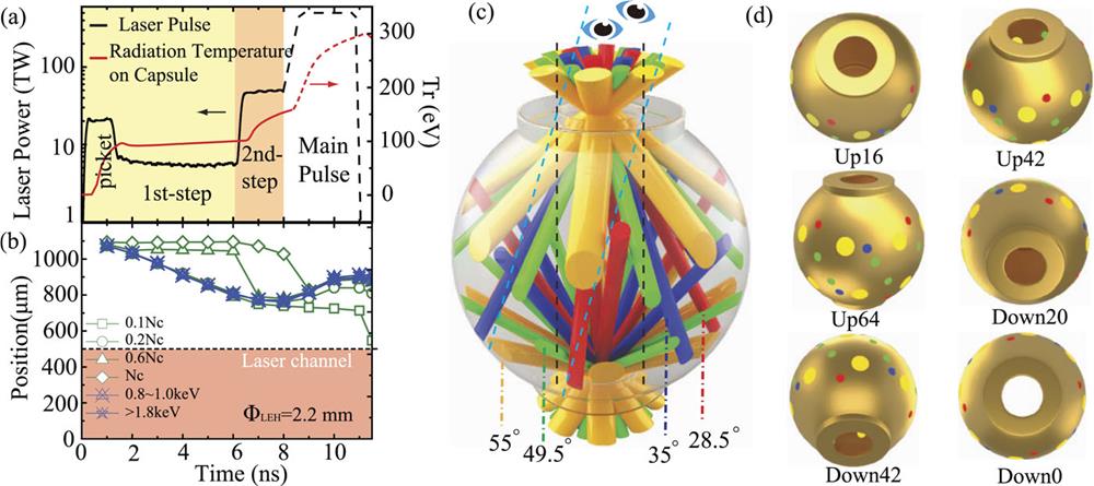
In the experiment, we consider an Au octahedral hohlraum of ignition-scale ΦH = 8.8 mm for a high-foot ignition scheme.55 Note that LEH closure is caused mainly by radiation ablation if there is sufficient LEH clearance for the laser beams. In this case, a 2-LEH hohlraum has similar LEH closure behavior to a 6-LEH hohlraum under the same radiation drive. Hence, it is reasonable to use an ignition-scale hohlraum with two LEHs for this experiment. The hohlraum is initially filled with 1.3 mg/cm3 C5H12 gas at 0.4 atm pressure and room temperature. The required radiation temperature Tr and drive laser from LARED-Integration are presented in Fig. 1(a) for ΦLEH = 2.2 mm. As can be seen, the prepulse is composed of a picket, a first step, and a second step, with a laser power lower than 50 TW. The first and second steps start at 1.49 and 6 ns, respectively. The main pulse starts at 8.2 ns, rising rapidly to 500 TW within 0.8 ns. From postprocessing of 2D simulations, we can define various plasma interface positions for the LEH. As can be seen in Fig. 1(b), for all values of the electron density except for the very low Ne = 0.1Nc, the LEH radius keeps closing during the whole prepulse and then opens up after the main pulse starts, similar to what is shown in Fig. 5 of Ref. 52. Here, Nc is the laser critical density, ∼1.1 × 10²¹/λ2 cm−3, where the laser wavelength λ is in micrometers. From 2D simulations, the beams have LEH clearance at ΦLEH ≥ 2.2 mm, but they are severely blocked by LEH closure at ΦLEH = 1.4 mm.
![]()
Figure 1.(a) Required
The SGIII laser facility has an output of 180 kJ, an order of magnitude lower than the NIF, and is sufficiently flexible to create a ∼10 ns laser pulse with power up to 50 TW. Hence, we can determine the LEH size by creating the prepulse inside an ignition-scale hohlraum with an ignition-scale laser beam size at SGIII. SGIII has 48 laser beams with injection angles of 28.5°, 35°, 49.5°, and 55°. Here, 55° happens to be the design angle of the octahedral hohlraum.19–22 The laser pointing error is 0.07 mm. Figure 1(c) shows a schematic of the 2-LEH spherical hohlraum injected by the 48 laser beams for this experiment. Every beam has a round shape at its LEH, with a super-Gaussian spatial profile
III. DIAGNOSTICS AND DISCUSSION
Various diagnostics56 are used to provide experimental evidence to determine the LEH size. LEH closure is observed by an x-ray framing camera (XFC) through the upper LEH at 0° in two ranges of 0.8–1 keV (N-band emission of Au, mainly from the equilibrium region ablated by radiation) and 2–3 keV (M-band emission of Au, mainly from the nonequilibrium corona where most of the laser energy is absorbed). Time-integrated images of x-rays in 2–3 keV are also observed by a pinhole camera through the upper LEH at 16°. The x-ray emissions observed outside the LEH can provide important information on LEH closure. The x-ray fluxes of 0.1–5 keV are measured by an array of flat-response x-ray detectors (FXRDs) through the upper LEHs at 16°, 42°, and 64° and from the lower LEHs at 0°, 20°, and 42° with respect to the hohlraum axis. The M-band flux of x-rays
On the left of Fig. 2, we present the time-resolved raw XFC images for shot SGIII20170323148 with ΦLEH = 1.4 mm and shot SGIII20170324150 with ΦLEH = 2 mm. The bright ring-shaped regions in these images are contributed by x-ray emissions from the ablated plasmas of the LEH edge. As can be seen, the LEH closure behaves similarly in the two x-ray bands for the same shot, but very differently between the two shots. The LEH with ΦLEH = 1.4 mm closes before 6 ns and then opens up, while for ΦLEH = 2 mm it continues to close at all times. This difference can be seen more clearly in the middle panels of Fig. 2, in which we present images along the temporal profiles of the drive laser together with the nominal radiation temperature Tr. Here, Tr is derived from the fluxes measured by the FXRDs,31 varying with their fields of view. As can be seen, the LEH with ΦLEH = 1.4 mm opens up after 6 ns when the second step pulse arrives with a rapid rise in power to about 50 TW. By contrast, the LEH with ΦLEH = 2 mm continues to close throughout the pulse. From the XFC images, we can define the LEH radius as the central location of the sharp slope of the ring region,54 and we show the time variation of this radius on the right of Fig. 2 for shots with ΦLEH = 1.4 and 2 mm. It is obviously the high laser power of the second step that causes the transition from closure to opening up for ΦLEH = 1.4 mm and slows down the closure for ΦLEH = 2 mm. For comparison, we adopt this definition of the LEH radius in post-shot 2D simulations with LARED-Integration. The simulation results are also presented on the right of Fig. 2, from which it can be seen that they agree qualitatively with the observations.
![]()
Figure 2.(Left) Time-resolved raw images from an x-ray framing camera (XFC) at four different times and for two x-ray energy ranges of 0.8–1 and 2–3 keV for shot SGIII20170323148 with 1.4 mm diameter LEHs (upper) and shot SGIII20170324150 with 2 mm diameter LEHs (lower). (Middle) Drive laser power (light cyan dashed curve) and
Severe LEH closure for the case with ΦLEH = 1.4 mm is confirmed by the interesting x-ray images from the pinhole camera for time-integrated M-band emissions of 2–3 keV. As can be seen in Fig. 3(a), the pinhole image of shot SGIII20170323149 has a strong emission ring (orange) from the inner edge of the LEH to the outer part of the laser channel, indicating strong M-band emission from the dense and hot plasmas that are ablated from the LEH edge and heated either directly by the lasers or by the hotter plasmas in the laser channel via electron heat conduction. Between the orange region and the LEH center, especially around the central part of the laser channel, M-band emissions become weak (light blue and blue) because of the relatively low density of the very hot laser plasmas in this region. The image in Fig. 3(a) clearly reveals that the radiation-ablated plasmas from the LEH edge strongly influence the clearance of the laser channel for ΦLEH = 1.4 mm. The time-integrated M-band emission images for ΦLEH = 2 mm are quite different. As can be seen in Fig. 3(c), the time-integrated M-band emission is strong in a ring (light blue) between the LEH edge and the laser channel. The outer edge of this ring corresponds to the expanded LEH, which is too cold to emit many M-band x-rays, while the inner edge is at a low density and therefore is also unable to emit many M-band x-rays. The image in Fig. 3(c) clearly indicates that ΦLEH = 2 mm provides sufficient clearance for the laser beams. Compared with the XFC image at 2–3 keV for shot SGIII20170324150 in Fig. 2, the time-integrated emission of this light blue ring is contributed mainly by the LEH closure plasmas at around 6.5 ns and later times. It is worth mentioning that the clear physical characteristics revealed by the images in Figs. 3(a) and 3(c) can be used to distinguish whether an LEH is open or not.
![]()
Figure 3.(a) Time-integrated x-ray image at 2–3 keV observed by the pinhole camera at 16° from the upper side and (b) its field of view for shot SGIII20170323149 with 1.4 mm diameter LEHs. (c) and (d) Corresponding image and field of view for shot SGIII20170324150 with 2 mm diameter LEHs. The red dashed circle is the LEH edge and the yellow dashed circle is the outer boundary of the 1 mm diameter laser beam. Note that the size scales of the two images are different.
The severe LEH closure in the case of ΦLEH = 1.4 mm is also confirmed by the temporal behavior of the M-band fluxes measured by the MXRDs. As can be seen in Fig. 4, the severe LEH closure for ΦLEH = 1.4 mm leads to a strong M-band flux with very different temporal behavior from that for ΦLEH ≥ 1.8 mm. The M-band flux for ΦLEH = 1.4 mm rises rapidly at 6 ns when the second step laser arrives, but rises much more slowly for ΦLEH ≥ 1.8 mm. In addition, the maximum M-band flux for ΦLEH = 1.4 mm is about 18 times stronger than that for ΦLEH ≥ 1.8 mm. In particular, from the on-axis MXRD, it is found that the M-band flux is quite strong for ΦLEH = 1.4 mm, while it is at a low noise level for ΦLEH ≥ 1.8 mm, except in the case ΦLEH = 2.4 mm, which is somewhat abnormal. We have two shots for ΦLEH = 1.6 mm. For shot SGIII20201009152, similar to ΦLEH = 1.4 mm, the M-band flux from all MXRDs rises rapidly at 6 ns to a remarkably high maximum value. However, for shot SGIII20201010155, the M-band fluxes from all MXRDs behave similarly to those for ΦLEH ≥ 1.8 mm. This indicates that 1.6 mm may be a critical size for this model and that an LEH size ΦLEH ≥ 1.8 mm provides sufficient clearance for the laser beams. Thus, the measured M-band fluxes from MXRDs again provide strong evidence to determine the LEH size.
![]()
Figure 4.Temporal behaviors of the M-band fluxes measured by the six MXRDs for shots with Φ
In Fig. 5, we compare the behavior of Tr for different values of ΦLEH. As can be seen, for a given FXRD, Tr exhibits similar behavior for all shots with ΦLEH ≥ 1.8 mm, but there are remarkable differences in the case of ΦLEH = 1.4 mm. First, for all FXRDs, for ΦLEH = 1.4 mm, Tr rises more rapidly before the second step laser reaches its flat top and is much higher than that for ΦLEH ≥ 1.8 mm. Second, the Tr difference between on-axis and off-axis FXRDs for ΦLEH = 1.4 mm is significantly smaller than for ΦLEH ≥ 1.8 mm. This indicates that the accumulated plasmas at the LEH lead to strong x-ray emission and severe LEH closure for ΦLEH = 1.4 mm. Third, Tr for ΦLEH ≥ 1.8 mm continues to rise during the flat top of the second laser step and reaches a maximum when the laser ends, while Tr for ΦLEH = 1.4 mm begins to decrease soon after the second step laser starts. This is a strong indication of severe LEH closure for ΦLEH = 1.4 mm.
![]()
Figure 5.Temporal behavior of
It should be noted here that Tr for ΦLEH = 1.4 mm is much higher than for all other cases with larger ΦLEH. Normally, a smaller ΦLEH leads to a higher Tr inside the hohlraum because of lower radiation loss via the smaller LEH area. However, this is not the case for ΦLEH = 1.4 mm, where the small size of the LEHs causes parts of the laser beams with ΦQ = 1 mm to hit the LEH edge and the outer wall of the hohlraum, leading to strong x-ray emission outside the hohlraum. As a result, only part of the laser energy can be injected into the hohlraum, and a much lower Tr is generated inside the hohlraum than that measured by FXRDs outside the hohlraum. Thus, the much higher Tr for ΦLEH = 1.4 mm from the FXRDs indicates a much lower Tr inside the hohlraum than in the cases with LEH clearance. It is interesting to note that the highest Tr of this “LEH closure” shot comes from the Up64 FXRD, which, although it sees a low flux (as shown in Fig. 4) because it views at a large angle to the hohlraum axis, also sees the hot LEH plasmas.
For an “LEH clearance” shot, the Tr values from all off-axis FXRDs are very close. This can be easily understood from their fields of view in Fig. 1(d), which are largely or even fully occupied by re-emissions from the wall. Note that from Fig. 5, the maximum Tr of the “LEH clearance” shots does not seem to be so sensitive to ΦLEH once the differences of input laser energy are taken into account. In fact, from the energy balance, Tr increases about 3% from ΦLEH = 1.4 to 2.4 mm inside such a 2-LEH spherical hohlraum with ΦH = 8.8 mm, which is within the error bar of the FXRDs. We have two shots for ΦLEH = 1.6 mm, whose Tr from off-axis FXRDs behave similarly to that for ΦLEH ≥ 1.8 mm, although the Tr from the on-axis FXRD rises rapidly at around 6 ns. Again, this indicates that ΦLEH = 1.6 mm is a critical size for the model in this experiment. Considering the laser beam diameter of 1 mm at the LEHs and the laser pointing error of 0.07 mm, the LEH closure is less than 0.6 mm in diameter under the ignition prepulse used in this experiment, which is in agreement with NIF data. From the NIF, the measured LEH closure is about 0.515 mm in diameter according to Ref. 57 and 0.526 and 0.406 mm for the low-foot and high-foot schemes, respectively, according to Ref. 54. To leave enough room for the laser pointing accuracy, we determine that the LEH diameter should be 0.8 mm larger than the laser focal spot at the LEH.
IV. SUMMARY
We have proposed to use the prepulse of the ignition pulse to determine the LEH size for the ignition target via the LEH closure behavior at a small laser facility, and we have adopted this approach to determine the LEH size at the SGIII facility with convincing evidence from multiple diagnostics. As a result, we have found that it is safe to take an LEH 0.8 mm larger in diameter than the laser size at the LEH for the model in this experiment. Considering a laser with 1.2 mm diameter at the LEH, we can take ΦLEH = 2 mm for an ignition octahedral hohlraum. This means that the octahedral hohlraum has the same total LEH area as that of an NIF cylindrical hohlraum.13,58,59 The latter needs a larger LEH size for its inner beams, which are much larger than the outer beams44,54 to suppress the serious LPIs arising from their long propagation distances inside the hohlraum. Taking ΦLEH = 2 mm and assuming a laser backscatter of 10%, according to Tables I and II, 1.53 and 1.95 MJ are required to drive the 8.864 mm diameter and 11.08 mm diameter octahedral hohlraums, respectively,
Our work reported here has successfully demonstrated the feasibility of octahedral hohlraums for inertial confinement fusion and is crucially important for determining the appropriate dimensions for an octahedrally configured laser system to give a predictable and reproducible fusion gain.23 It has also provided a novel way to determine the LEH size for an ignition-scale target at a small-scale laser facility. Note that the LEH closure is related to the prepulse. Hence, if a prepulse can ablate more plasmas and lead to more severe LEH closure, then a larger LEH will be required. Point designs with octahedral hohlraums for NIF capsules CH Rev5 and Be Rev6 are presented in Refs. 52 and 60 respectively, and a paper on point design for the recently proposed novel ignition capsule61 is under preparation, which can mitigate the hydrodynamic instabilities by using CH as the outermost ablator layer, while keeps high-density carbon as the main ablator for maintaining the advantage of short laser pulses.
ACKNOWLEDGMENTS
Acknowledgment. The authors thank the entire SGIII operations, diagnostics, and target teams at the Research Center of Laser Fusion, China Academy of Engineering Physics for their outstanding support during the experiment. All simulations were performed on a supercomputer in China. We especially acknowledge all the referees of this paper for providing very beneficial and important suggestions and questions to improve the quality of the paper. This work is supported by the National Natural Science Foundation of China (Grant No. 12035002).
References
[1] J.Nuckolls, A.Thiessen, L.Wood, G.Zimmerman. Laser compression of matter to super-high densities: Thermonuclear (CTR) applications. Nature, 239, 139(1972).
[2] J.Lindl. Development of the indirect-drive approach to inertial confinement fusion and the target physics basis for ignition and gain. Phys. Plasmas, 2, 3933(1995).
[3] S.Atzeni, J.Meyer-ter-Vehn. The Physics of Inertial Fusion(2004).
[4] D.Clery. Laser-powered fusion effort nears ‘ignition. Science, 373, 841(2021).
[5] H.Abu-Shawareb, R.Acree, J.Adams, P.Adams, B.Addis, R.Aden et al. Lawson criterion for ignition exceeded in an inertial fusion experiment. Phys. Rev. Lett., 129, 075001(2022).
[6] D. A.Callahan, D. T.Casey, O. A.Hurricane, A. L.Kritcher, J. E.Ralph, A. B.Zylstra et al. Experimental achievement and signatures of ignition at the National Ignition Facility. Phys. Rev. E, 106, 025202(2022).
[7] D. A.Callahan, D. S.Clark, O. A.Hurricane, A. L.Kritcher, C. R.Weber, A. B.Zylstra et al. Design of an inertial fusion experiment exceeding the Lawson criterion for ignition. Phys. Rev. E, 106, 025201(2022).
[8] E. M.Campbell, W. J.Hogan. The National Ignition Facility—Applications for inertial fusion energy and high-energy-density science. Plasma Phys. Controlled Fusion, 41, B39(1999).
[9] J. M.Auerbach, M. W.Bowers, S. N.Dixit, G. V.Erbert, C. A.Haynam, P. J.Wegner et al. National Ignition Facility laser performance status. Appl. Opt., 46, 3276(2007).
[10] A. L.Kritcher, M. E.Martin, J.Nilsen, D. C.Swift, R. E.Tipton, H. D.Whitley et al. Understanding the effects of radiative preheat and self-emission from shock heating on equation of state measurement at 100s of Mbar using spherically converging shock waves in a NIF hohlraum. Matter Radiat. Extremes, 5, 018401(2020).
[11] P.Michel et al. Tuning the implosion symmetry of ICF targets via controlled crossed-beam energy transfer. Phys. Rev. Lett., 102, 025004(2009).
[12] R. L.Berger, E.Bond, D. K.Bradley, L.Divol, P.Michel, J. D.Moody et al. Multistep redirection by cross-beam power transfer of ultrahigh-power lasers in a plasma. Nat. Phys., 8, 344-349(2012).
[13] D. A.Callahan, O. A.Hurricane, A. L.Kritcher, J. E.Ralph, H. F.Robey, A. B.Zylstra et al. Burning plasma achieved in inertial fusion. Nature, 601, 542(2022).
[14] E.Dewald, L.Divol, S.Glenzer, R. K.Kirkwood, J.Kline, J. D.Moody et al. A review of laser-plasma interactions physics of indirect drive fusion plasma. Plasma Phys. Controlled Fusion, 55, 103001(2013).
[15] E. L.Dewald, F.Hartemann, M.Hohenberger, P.Michel, J.Milovich, A.Pak et al. Generation and beaming of early hot electrons onto the capsule in laser-driven ignition hohlraums. Phys. Rev. Lett., 116, 075003(2016).
[16] F. P.Condamine, T.Gong, N.Jourdain, K. Q.Pan, O.Renner, V. T.Tikhonchuk et al. Studies of laser-plasma interaction physics with low-density targets for direct-drive inertial confinement fusion on the Shenguang III prototype. Matter Radiat. Extremes, 6, 025902(2021).
[17] T. R.Boehly, V. N.Goncharov, J. P.Knauer, P.McKenty, S.Skupsky, V. A.Smalyuk et al. A model of laser imprinting. Phys. Plasmas, 7, 2062(2000).
[18] D. S.Clark, E. L.Dewald, L.Divol, L. F. B.Hopkins, A.Pak, C. R.Weber et al. Impact of localized radiative loss on inertial confinement fusion implosions. Phys. Rev. Lett., 124, 145001(2020).
[20] X.-T.He, D.Lai, K.Lan, J.Liu, W.Zheng. High flux symmetry of the spherical hohlraum with octahedral 6LEHs at the hohlraum-to-capsule radius ratio of 5.14. Phys. Plasmas, 21, 010704(2014).
[21] X.-T.He, D.Lai, K.Lan, J.Liu, W.Zheng. Octahedral spherical hohlraum and its laser arrangement for inertial fusion. Phys. Plasmas, 21, 052704(2014).
[22] K.Lan, W.Zheng. Novel spherical hohlraum with cylindrical laser entrance holes and shields. Phys. Plasmas, 21, 090704(2014).
[23] K.Lan. Dream fusion in octahedral spherical hohlraum. Matter Radiat. Extremes, 7, 055701(2022).
[24] Y.Chen, W.Huo, K.Lan, Z.Li, J.Liu, X.Xie et al. Progress in octahedral spherical hohlraum study. Matter Radiat. Extremes, 1, 8(2016).
[25] W.Huo, K.Lan, Z.Li, J.Liu, G.Ren, D.Yang et al. First demonstration of improving laser propagation inside the spherical hohlraums by using the cylindrical laser entrance hole. Matter Radiat. Extremes, 1, 2(2016).
[26] W. Y.Huo, K.Lan, S.Li, Z.Li, J.Liu, G.Ren, D.Yang et al. Comparison of the laser spot movement inside cylindrical and spherical hohlraums. Phys. Plasmas, 24, 072711(2017).
[27] Y. H.Chen, K.Lan, Z.Li, X.Xie, C.Zhai, C.Zheng et al. Experimental demonstration of low laser-plasma instabilities in gas-filled spherical hohlraums at laser injection angle designed for ignition target. Phys. Rev. E, 95, 031202(R)(2017).
[28] Y.Chen, L.Hao, Z.Li, X.Xie, C.Zhai, C.Zheng et al. First experimental comparisons of laser-plasma interactions between spherical and cylindrical hohlraums at SGIII laser facility. Matter Radiat. Extremes, 2, 77(2017).
[29] Y. H.Chen, W. Y.Huo, K.Lan, Z.Li, J.Liu, X.Xie et al. First investigation on the radiation field of the spherical hohlraum. Phys. Rev. Lett., 117, 025002(2016).
[30] Y.Huang, L.Jing, S.Li, Z.Li, X.Xie, D.Yang et al. Radiation flux study of spherical hohlraums at the SGIII prototype facility. Phys. Plasmas, 23, 112701(2016).
[31] H.Cao, Y.-H.Chen, W. Y.Huo, Z.Li, G.Ren, X.Xie et al. First octahedral spherical hohlraum energetics experiment at the SGIII laser facility. Phys. Rev. Lett., 120, 165001(2018).
[32] H.Cao, Y.Chen, Y.Dong, K.Lan, Z.Li, J.Wu et al. First inertial confinement fusion implosion experiment in octahedral spherical hohlraum. Phys. Rev. Lett., 127, 245001(2021).
[33] L.Ren, D.Zhao, J.Zhu. Beam guiding system geometric arrangement in the target area of high-power laser drivers. High Power Laser Sci. Eng., 3, e12(2015).
[34] A.Casner, P.Gauthier, P. E.Masson-Laborde, M. C.Monteil, F.Philippe, V.Tassin et al. Laser plasma interaction on rugby hohlraum on the Omega Laser Facility: Comparisons between cylinder, rugby, and elliptical hohlraums. Phys. Plasmas, 23, 022703(2016).
[35] P. A.Amendt, W. A.Farmer, J. H.Hammer, D. E.Hinkel, M.Tabak. High-temperature hohlraum designs with multiple laser-entrance holes. Phys. Plasmas, 26, 032701(2019).
[37] S.Craxton. A new beam configuration to support both spherical hohlraums and symmetric direct drive.
[38] R. S.Craxton, W. Y.Wang. Pentagonal prism spherical hohlraums for OMEGA. Phys. Plasmas, 28, 062703(2021).
[40] J.Bastian, A.Casner, D.Galmiche, J. P.Jadaud, S.Laffite, M.Vandenboomgaerde et al. Prolate-spheroid (“rugby-shaped”) hohlraum for inertial confinement fusion. Phys. Rev. Lett., 99, 065004(2007).
[41] D.Lai, K.Lan, X.Li, Y.Zhao. Initial study and design on ignition ellipraum. Laser Part. Beams, 30, 175(2012).
[42] L. F.Berzak Hopkins, S.Bhandarkar, E. L.Dewald, L.Divol, S.Le Pape, A.Pak et al. Fusion energy output greater than the kinetic energy of an imploding shell at the National Ignition Facility. Phys. Rev. Lett., 120, 245003(2018).
[43] P.Amendt, D.Ho, S.Khan, J.Lindl, Y.Ping, V.Smalyuk et al. Ultra-high
[44] D. A.Callahan, D. S.Clark, S. W.Haan, B. A.Hammel, J. D.Lindl, J. D.Salmonson et al. Point design targets, specifications, and requirements for the 2010 ignition campaign on the National Ignition Facility. Phys. Plasmas, 18, 051001(2011).
[45] P.Gu, X.-T.He, W.Huo, D.Lai, K.Lan, X.Li, G.Ren, C.Wu. An initial design of hohlraum driven by a shaped laser pulse. Laser Part. Beams, 28, 421(2010).
[46] R.Pakula, S.Sakabe, R.Sigel, G. D.Tsakiris. X-ray generation in a cavity heated by 1.3 or 0.44 mm laser light III Comparison of the experimental results with theoretical predictions for x-ray confinement. Phys. Rev. A, 38, 5779-5785(1988).
[47] T.Feng, D.Lai, K.Lan, X.Meng, Y.Xu. Study on two-dimensional transfer of radiative heating wave. Laser Part. Beams, 23, 275(2005).
[48] J.-F.Gu, P.-J.Gu, X.-D.Hang, S.Jiang, D.-G.Kang, P.Song, H.Yong, C.-L.Zhai. Numerical simulation of 2-D radiation-drive ignition implosion process. Commun. Theor. Phys., 59, 737(2013).
[49] Y.Gao, D.Lai, K.Lan, Y.Li, W.Pei. Radiation-temperature shock scaling of 1 ns laser-driven hohlraums. Phys. Plasmas, 17, 042704(2010).
[50] W. Y.Huo, K.Lan, S.Li, X.Li, Y.Li, D.Yang et al. Determination of the hohlraum M-band fraction by a shock-wave technique on the SGIII-prototype laser facility. Phys. Rev. Lett., 109, 145004(2012).
[51] K.Lan, X.Qiao. Study of high-Z-coated ignition target by detailed configuration accounting atomic physics for direct-drive inertial confinement fusion. Plasma Phys. Controlled Fusion, 61, 014006(2019).
[52] H.Cao, Y.-H.Chen, K.Lan, C.Zhai, C.Zheng. Design of octahedral spherical hohlraum for CH Rev5 ignition capsule. Phys. Plasmas, 24, 082701(2017).
[53] J.Edwards, O.Landen, J.Lindl, E.Moses. Review of the National Ignition Campaign 2009-2012. Phys. Plasmas, 21, 020501(2014).
[54] J. H.Hammer, S. A.MacLaren, N. B.Meezan, M. B.Schneider, K.Widmann, B. E.Yoxall et al. The size and structure of the entrance hole in gas-filled hohlraums at the National Ignition Facility. Phys. Plasmas, 22, 122705(2015).
[55] D. A.Callahan, D. T.Casey, P. M.Celliers, C.Cerjan, E. L.Dewald, O. A.Hurricane et al. Fuel gain exceeding unity in an inertially confined fusion implosion. Nature, 506, 343(2014).
[56] Y.Ding, S.Jiang, S.Li, S.Liu, F.Wang, J.Yang et al. Recent diagnostic developments at the 100 kJ-level laser facility in China. Matter Radiat. Extremes, 5, 035201(2020).
[57] J.Lindl. Overview and status of the National Ignition Campaign on the NIF.
[58] L. F.Berzak Hopkins, L.Divol, D. D.Ho, S.Le Pape, A. J.Mackinnon, N. B.Meezan et al. First high-convergence cryogenic implosion in a near-vacuum hohlraum. Phys. Rev. Lett., 114, 175001(2015).
[59] D. A.Callahan, O. A.Hurricane, A. L.Kritcher, A. B.Zylstra et al. Achieving record hot spot energies with large HDC implosions on NIF in HYBRID-E. Phys. Plasmas, 28, 072706(2021).
[60] Y.-H.Chen, K.Lan, Y.Li, J.Liu, G.Ren, C.Zhai. Octahedral spherical hohlraum for Rev. 6 NIF beryllium capsule. Phys. Plasmas, 25, 102701(2018).
[61] K.Lan, X.Qiao. Novel target designs to mitigate hydrodynamic instabilities growth in inertial confinement fusion. Phys. Rev. Lett., 126, 185001(2021).


Set citation alerts for the article
Please enter your email address

© Copyright 2018-2021 | Chinese Laser Press. All Rights Reserved 沪ICP备15018463号-20